
Active Power Factor Correction Circuit

The power factor correction (PFC) circuit is a critical component in modern electronic systems, particularly for applications requiring efficient energy management and compliance with regulatory standards. The circuit typically begins with an AC input, which is rectified using a diode bridge to convert the AC voltage to DC. This process, while effective, can lead to significant harmonic distortion if not managed properly.
To mitigate this, the PFC circuit employs a boost converter topology. The boost converter consists of an inductor, a switch (usually a MOSFET), a diode, and an output capacitor. During the switch's ON state, current flows through the inductor, storing energy. When the switch is turned OFF, the inductor releases its stored energy to the load through the diode, which results in a higher output voltage than the input voltage. This operation not only increases the DC voltage but also shapes the input current to be more sinusoidal, thus improving the power factor.
The inclusion of inrush current detection is crucial for protecting the circuit during startup, preventing damage from sudden surges. Overcurrent protection ensures that the circuit operates within safe limits, while overvoltage and undervoltage protection circuits safeguard the connected load from voltage fluctuations.
The design also emphasizes the use of smaller inductors and MOSFETs, which contribute to a reduction in overall system size and cost. By optimizing component selection and layout, the PFC circuit achieves high efficiency and reliability, fulfilling the stringent requirements of energy regulations while minimizing operational costs.
Overall, the power factor correction circuit is essential for enhancing the efficiency of power conversion systems and ensuring compliance with international standards, making it a vital consideration in the design of modern electrical devices.Active power factor correction stabilize the electrical demand of a device to give the best power factor characteristic of many types of loads. To meet power factor regulation, a low cost solution should be designed. In many application, the need of high DC voltage is usually implemented by a direct rectification of the AC line followed by bulk ca
pacitor filtering. This capacitor filtering introduce current spike that distort the power line sine waveform, and this introduce a poor power factor, resulting in an apparent input power that is much higher than the real power. This can be solved by inserting a pre-regulation between the rectifier and the bulk capacitor. We call this pre-regulator circuit as power factor correction circuit. Here is the schematic diagram of the circuit: This power factor controller is a low cost system solution for boost mode follower.
that meets IEC1000 3 2 standard. This power factor correction circuit includes an inrush current detection, protection against overcurrent, overvoltage and undervoltage. Follower boost mode for system cost reduction smaller inductor and MOSFET can be used. [Circuit schematic source: ON Semiconductor Application Notes] We aim to transmit more information by carrying articles.
Please send us an E-mail to wanghuali@hqew. net within 15 days if we are involved in the problems of article content, copyright or other problems. We will delete it soon. 🔗 External reference
Related Circuits
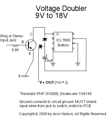
If you want to try a higher voltage with your pedals, try this simple and easy voltage doubler circuit which uses an ICL7660 CMOS Voltage Converter Chip. I have found that JFETs such as the J201 sound much better...
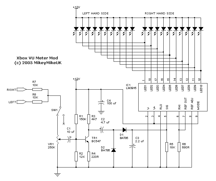
The LED current drive is regulated and programmable, which eliminates the need for current-limiting resistors. The integrated circuit (IC) features an adjustable voltage reference and an accurate ten-step voltage divider. The LED current drive circuit is designed to provide precise...
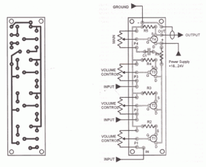
This FET audio mixer demonstrates the versatility of FETs. Originally designed for high-frequency applications, FETs can also effectively handle audio frequencies, showcasing exceptional performance in this domain. The circuit can accommodate an unlimited number of inputs, provided that the...

This lie detector circuit provides two readings: one for difficult questions and another for the subject's general emotional state. Two flexible, uninsulated wires wrapped around the fingers or wrist can serve as electrodes. Each change in resistance, and consequently...
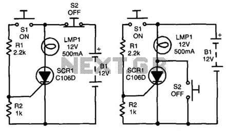
In both circuits, the SCR (Silicon Controlled Rectifier) and the lamp can be latched on by momentarily closing switch S1, which provides gate drive to the SCR through resistor R1. In both configurations, the gate is connected to the...
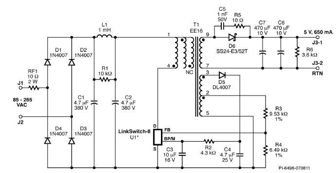
A simple 3.25W constant voltage/constant current (CV/CC) charger can be designed using the LinKSwitch family IC manufactured by Power Integrations. This electronic circuit project is intended to provide a 5-volt output with a maximum current of 650mA. The 3.25W...