
FET audio mixer circuit

The FET audio mixer circuit utilizes Field Effect Transistors (FETs) to achieve high fidelity audio mixing. The use of FETs in this application is advantageous due to their high input impedance and low output impedance, which minimizes signal loss and distortion. The mixer can be configured to accept multiple audio signals, such as those from microphones or musical instruments, and combine them into a single output signal.
In this circuit, the input signals are fed into the gate terminals of the FETs. Each FET acts as a variable resistor, controlled by the voltage at the gate, allowing for precise mixing of the audio signals. The formula for R1 ensures that the input impedance remains suitable for the desired number of inputs, preventing loading effects that could degrade audio quality.
The output of the mixer can be connected to a power amplifier or directly to a recording device, depending on the application. Additionally, the design can incorporate features such as volume controls for each input channel, allowing for further customization of the audio mix.
To enhance performance, bypass capacitors may be added to filter out any unwanted noise and to stabilize the power supply. The layout of the circuit should be carefully considered to minimize interference and maintain signal integrity, particularly in environments with high electromagnetic interference.
Overall, this FET audio mixer exemplifies the effective use of FET technology in audio applications, offering flexibility and high performance for a variety of mixing needs.This FET audio mixer is an example of FET`s versatility. FETs are originally designed for high frequency applications but they can be used for audio frequencies and in fact they perform excellently in this area. The number of inputs that can be connected to the circuit is unlimited as long as the R1 value is chosen according to this formula: R1 =
22K / n, where n = the number of inputs. 🔗 External reference
Related Circuits
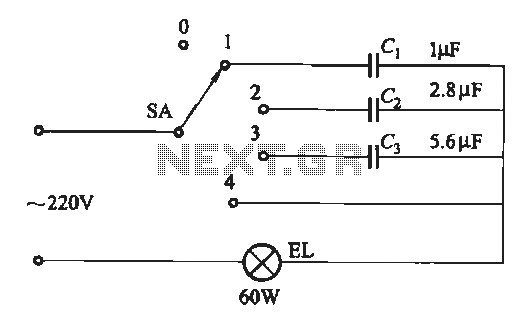
A dimming circuit capacitor circuit is illustrated in Figure 2-63. When the switch SA is moved from position "1" to "3," the capacitance increases in ascending order, resulting in the light bulb brightness also increasing correspondingly. When SA is...
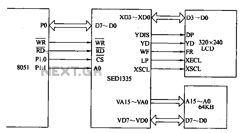
The MCS-51 series single-chip interface circuit 8051 is utilized to control the SED1335 35 dot matrix LCD display. This controller can manage up to a 640x256 dot matrix LCD display for both graphics and character representation, with the capability...
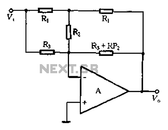
At high frequencies, the capacitor Cz can be considered a short circuit (i.e., the resistance of the RPi is negligible). This is illustrated in Figure 4-6 (a) of the apparatus, which corresponds to the equivalent circuit shown in Figure...
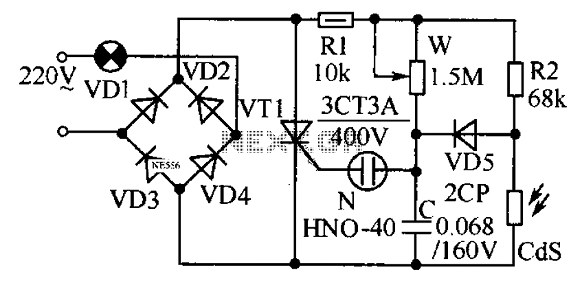
This circuit is designed to automatically adjust the brightness of lights based on the ambient light intensity. In bright conditions, the lights remain off, while in low ambient brightness, the lights are activated. The circuit incorporates a thyristor (VT1)...
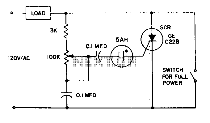
The 5AH will trigger when the voltage across the two 0 µF capacitors reaches the breakdown voltage of the lamp. Control can be obtained from full off to 95% of the half-wave RMS output voltage. Full power can be...
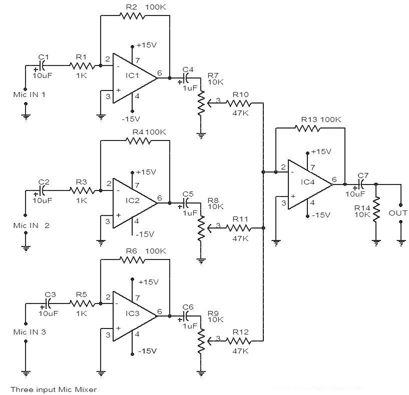
This is a circuit diagram of a 741 IC-based three-input microphone mixer circuit. A total of four 741 ICs are utilized, with IC1, IC2, and IC3 serving specific functions within the design. The circuit utilizes four operational amplifiers from the...