
Adjustable Timer circuit 1-10 minute

The Adjustable Timer circuit is designed to provide a visual and audible indication of elapsed time. It typically consists of a microcontroller or timer IC, a resistor-capacitor (RC) timing network, two light-emitting diodes (LEDs), and a sound-generating component such as a piezo buzzer.
The circuit operates by first charging a capacitor through a resistor, which defines the time period. The microcontroller monitors the voltage across the capacitor and determines when it has reached a predefined threshold, indicating that the time period has expired. At this point, the microcontroller deactivates the green LED and activates the red LED and the bleeper, signaling the end of the timing cycle.
The adjustable feature of the timer may be implemented using a potentiometer in the RC timing network, allowing the user to set the desired time period. The circuit may also include a reset button to restart the timing process at any point.
In application, this circuit is suitable for various timing tasks, such as cooking timers, reminders, or other countdown applications where visual and audible alerts are beneficial. Proper design considerations should be made for component selection to ensure reliability and accuracy in timing operations.The Adjustable Timer circuit starts timing when switched on. The green LED lights to show that timing is in progress. When the time period is over the green LED turns off, the red LED turns on and the bleeper sounds. The time period is set.. 🔗 External reference
Related Circuits

Integrate an inexpensive stopwatch into this circuit to create an accurate reaction timer. The circuit is connected in parallel with the start/stop button of the watch through a 2.5mm socket, which fits securely in one corner of the casing....
The clock circuit above uses seven ICs and 19 LEDs to indicate binary coded decimal time. The LEDs can be arranged so that each horizontal group of 3 or 4 LEDs represents a decimal digit between 0 and 9...
An isolation transformer and a variable auto transformer, very much like a Variac. Fuse 1 protects against gross overload. Lamp 1, across the Fuse 1, is a red incandescent pilot lamp and it lights up in the event of...
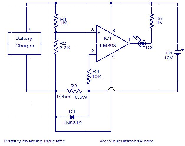
This simple circuit can be used to monitor whether a battery is charging. The voltage comparator IC LM393 is the core component of this circuit. The LED D1 will remain ON whenever there is at least 25 milliampere current...
A rain sensor alarm circuit is a useful device for alerting when rainfall occurs. The rain detector circuit presented is straightforward, utilizing only three components while maintaining high sensitivity to detect rain or moisture. The sensor can be constructed...

This amplifier is designed with the following specifications: distortion less than 0.1% at full power of 100W even at 20KHz, with power attributed to an extended bandwidth. The output transistors are protected against short circuits, and the power supply...