
Advanced LED Temperature Indicator
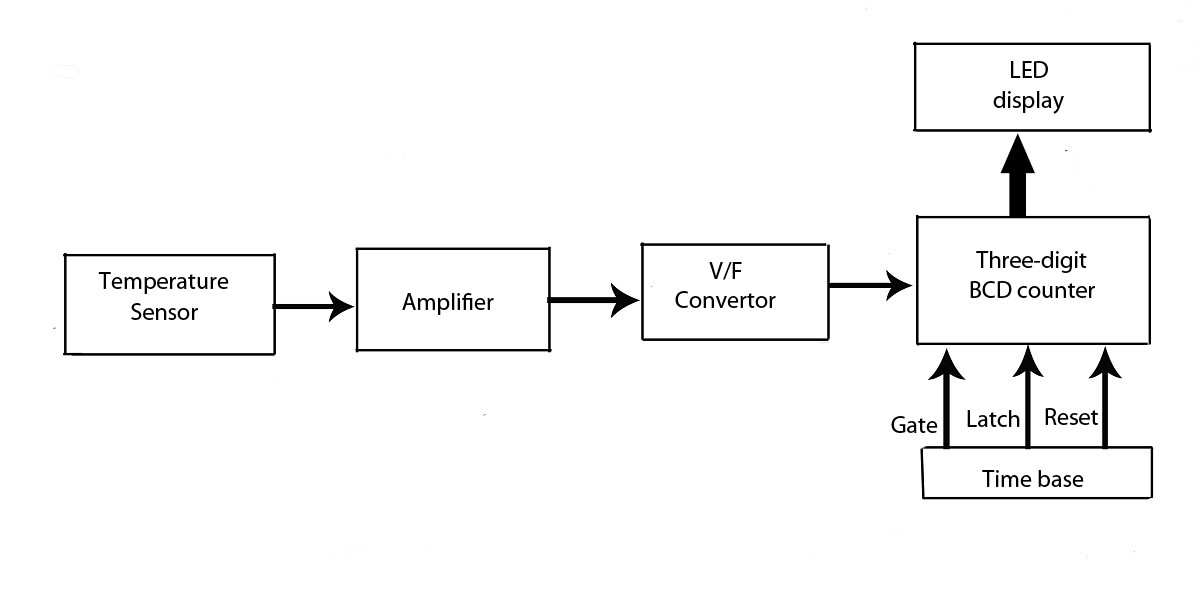
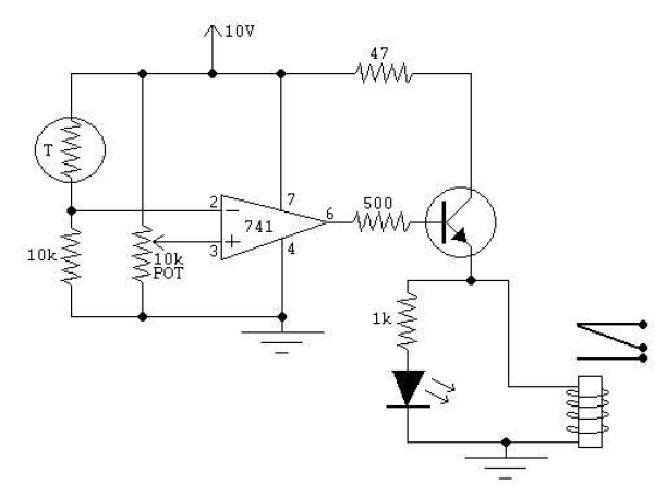
The LED display temperature indicator is designed to provide a clear visual representation of temperature readings. The circuit typically includes a temperature sensor, such as a thermistor or an LM35 temperature sensor, which converts temperature into an electrical signal. This signal is then processed by a voltage-to-frequency converter, which transforms the voltage output from the sensor into a frequency signal proportional to the temperature.
The frequency output can be fed into a microcontroller or a frequency counter that interprets the signal and drives an LED display, allowing users to read the temperature in real-time. Additional components may include resistors, capacitors, and a power supply unit to ensure stable operation of the circuit.
In terms of assembly, the circuit can be constructed on a breadboard for prototyping, with careful consideration given to the layout to minimize noise and interference. Proper calibration of the system is essential to ensure accurate temperature readings, which may involve adjusting the V/F converter settings based on the characteristics of the chosen temperature sensor.
This project serves as an educational tool for understanding the principles of temperature measurement and digital display technology, making it suitable for both hobbyists and students in electronics.this verified project provide idea, circuit and working of the system LED display temperature indicator. Digital temperature indicator.using V/F converter.various electronics project. 🔗 External reference
Related Circuits
This project page has evolved into a design discussion. Constructive suggestions and collaboration are still welcome. Please refer to the comments section. The project focuses on the development of an electronic circuit design, which has transitioned from a simple project...
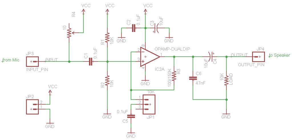
The TL072 operational amplifier is used to amplify an audio signal that is directed to both speakers and an Arduino's analog input. The amplifier is powered by a 12V, 2A wall wart, which is also regulated down to 5V...
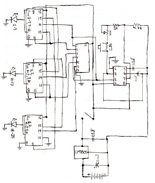
Here is the schematic for the circuit. Solder all the components onto a perfboard. The drawings may not be very clear. Essentially, the 555 timer generates a pulse. The circuit utilizes a 555 timer IC configured in astable mode, which...
There is no prior experience in building controllers, and there is uncertainty about how to begin. A budget constraint of less than 100 euros is present. A power thyristor is already available. The inquiry revolves around the best method...
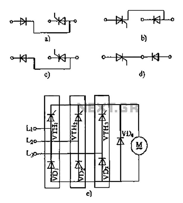
The thyristor linking arm rectifier module is a three-phase half-controlled bridge rectifier circuit. The thyristor-rectifier module linking arm consists of a thyristor and a rectifier diode connected in series or parallel, designed to fulfill specific requirements in power circuits....
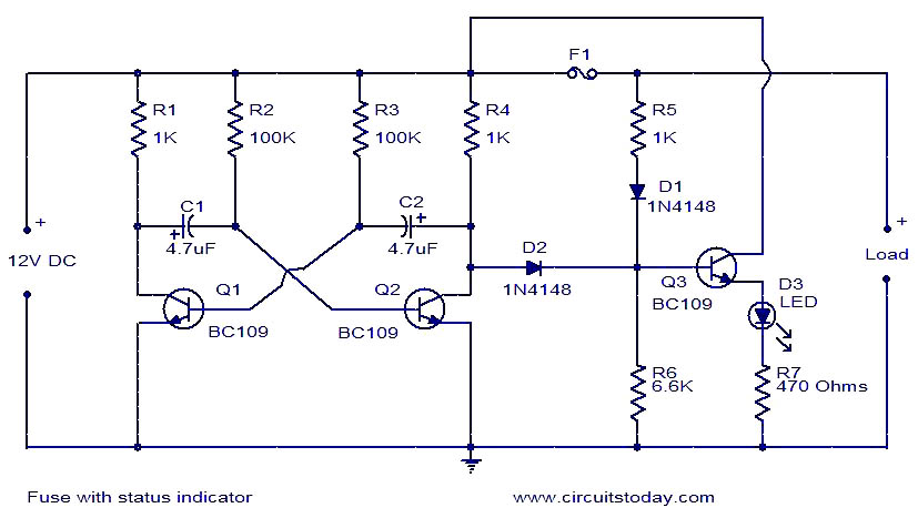
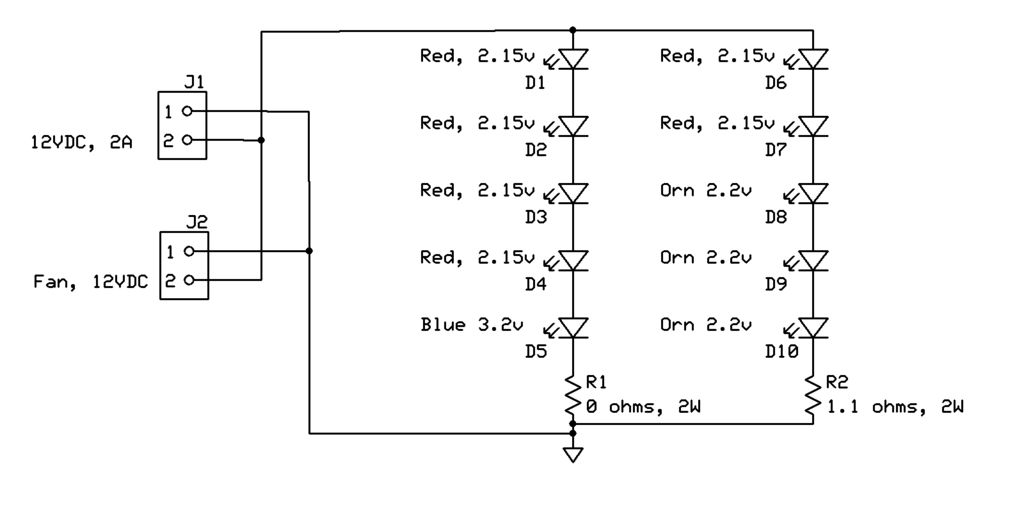
The circuit diagram presented illustrates a fuse with an automatic status indicator, designed for operation with a 12V DC supply. While the fuse remains intact, the LED D3 emits a continuous glow; however, if the fuse blows, the LED...