
Thyristor - linking arm rectifier module three-phase half-controlled bridge rectifier circuit

The three-phase half-controlled bridge rectifier circuit utilizes a combination of thyristors and diodes to convert alternating current (AC) to direct current (DC). In this configuration, two thyristors are used for the positive half-cycle of the input AC waveform, while two diodes handle the negative half-cycle. This arrangement allows for controlled rectification, enabling the adjustment of output voltage by varying the firing angle of the thyristors.
In a typical application, the thyristor linking arm module can be employed in industrial power supplies, motor drives, and other systems requiring efficient power conversion. The thyristors are triggered by a control circuit, which determines the timing of the conduction phase, thereby regulating the amount of power delivered to the load. The rectifier diodes provide a path for current during the negative cycle, ensuring continuous operation and reducing ripple in the output DC voltage.
The linking arm design facilitates modularity, allowing for easy integration into various power systems. The series or parallel configuration of the thyristors and diodes can be adapted based on the specific voltage and current requirements of the application. This flexibility makes the thyristor linking arm rectifier module a versatile choice for engineers and designers working on power electronics projects.
In summary, the thyristor linking arm rectifier module is an essential component in modern power electronics, providing an effective means of controlling and converting electrical energy for a wide range of applications. As shown thyristors - linking arm rectifier module three-phase half-controlled bridge rectifier circuit. Thyristor - rectifier module linking arm is made of a thyristor and a r ectifier diode in series or in parallel through the building blocks to meet the needs of some of the power circuit, the common-linked arm module as shown in FIG.
Related Circuits
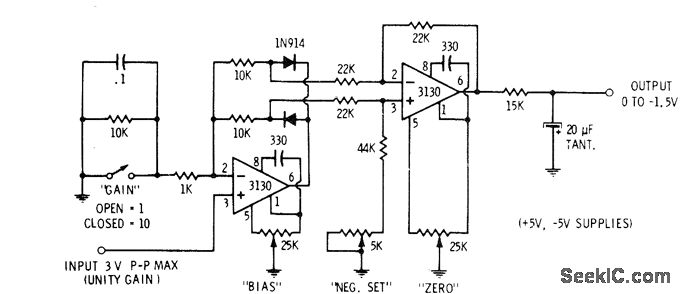
This circuit is utilized in digital voltmeters to convert an AC waveform into a full-wave rectified DC equivalent. The first operational amplifier (op-amp), designated as 3130, functions as a polarity separator. Negative-going signals appear across the upper 10K resistor,...
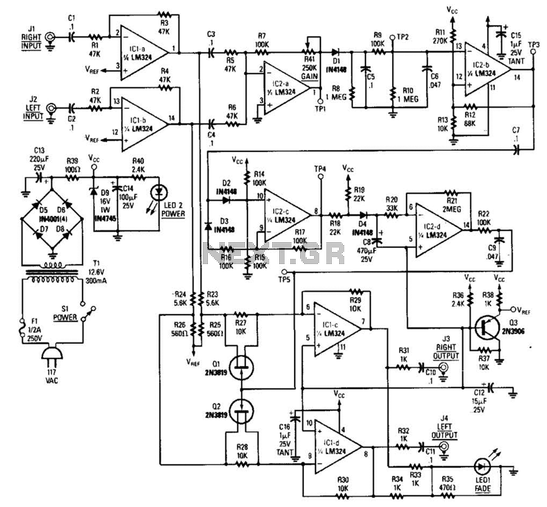
The LR inputs are summed, processed, and then drive a comparator. This comparator detects levels and generates transitions when audio inputs exceed or fall below predetermined thresholds. The frequency of these transitions, which correspond to rapid volume changes, is...
This circuit automatically controls the headlight of a motorcycle, turning it on and off independently of the light and ignition switches, as long as the battery is fully charged. The initial stage employs a 220-ohm resistor and ZD1 to...
The remote control robot circuit is illustrated in the accompanying figure. Figure 2-36(a) presents the circuit diagram, while figure 2-36(b) depicts the operating timing diagram. The robot's rotation process involves an ultrasonic launching circuit, which consists of a 40...
FIG. 284 illustrates a practical emergency power lighting system that activates automatically in the event of a sudden power outage. The fluorescent lights serve as emergency lighting. If the primary illumination lamp is turned off due to a power...

A Zener diode can be used for over-voltage protection, which may resolve the issue at hand. If the failure is due to over-voltage on VDDA, the Zener diode will assist. However, with a 12V rail, significant ringing would be...