
Arduino SD Cards and Datalogging
The project involves the integration of an SD card shield with a microcontroller to create a data logger capable of recording sensor data. The SD card shield serves as an interface for data storage, allowing for the reading and writing of data in a structured format. The microcontroller, typically an Arduino or similar platform, will handle the logic and control necessary for data acquisition from the sensors.
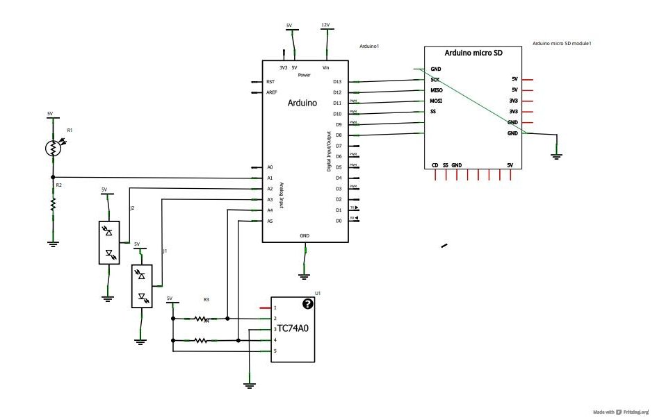
To begin, the wiring of the SD card shield to the microcontroller must be established. This typically involves connecting the SPI pins (MOSI, MISO, SCK) and a chip select (CS) pin, along with power and ground connections. The specific pin configuration can vary based on the microcontroller used and the design of the shield.
Once the hardware setup is complete, the software component involves initializing the SD card and establishing communication protocols. The microcontroller code will include libraries specific to SD card operations, enabling functions for file creation, data writing, and data reading. The sensors, which may include temperature, humidity, or pressure sensors, will be connected to the microcontroller's analog or digital input pins, depending on their output type.
The data logger will periodically read values from the sensors, format them appropriately, and write them to a file on the SD card. This process can be managed using timers or interrupts to ensure consistent data collection intervals. The recorded data will be stored in a CSV (Comma-Separated Values) format, which is compatible with data analysis tools such as Microsoft Excel.
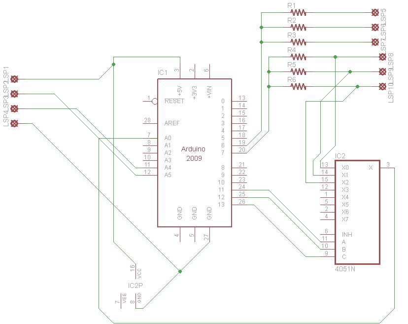
The use of Fritzing to create circuit schematics allows for a visual representation of the connections and components involved in the project. It is advisable to refer to these schematics while implementing the project to ensure accurate wiring and component placement.
In summary, this project not only reinforces the fundamental concepts learned in previous tutorials but also provides practical experience in integrating various components to create a functional data logging system. The outcome will facilitate data collection and analysis, enhancing understanding of sensor behavior and data interpretation.Now that we`ve covered the basics in tutorials 1-10 (you have watched them all right! ), it`s time to start pursuing some more complex projects! In this episode, we`ll utilize an SD card shield from cooking-hacks. com to create a datalogger. First, I`ll walk you through the process of reading from, and writing to an SD card. Then, we`ll utilize som e of our knowledge from tutorials 4, 6, 7, and 8 to add several sensors that we can poll periodically using our datalogger. The logger will record sensor values to its SD card in a useful format so that we can later use a computer program like Microsoft Excel to visualize the data.
Download the schematics and source code first so you can reference them while you watch the video. For the first time, I`m using fritzing to draw the circuit schematics. So, take a look at them, and let me know what you think! 🔗 External reference
Related Circuits
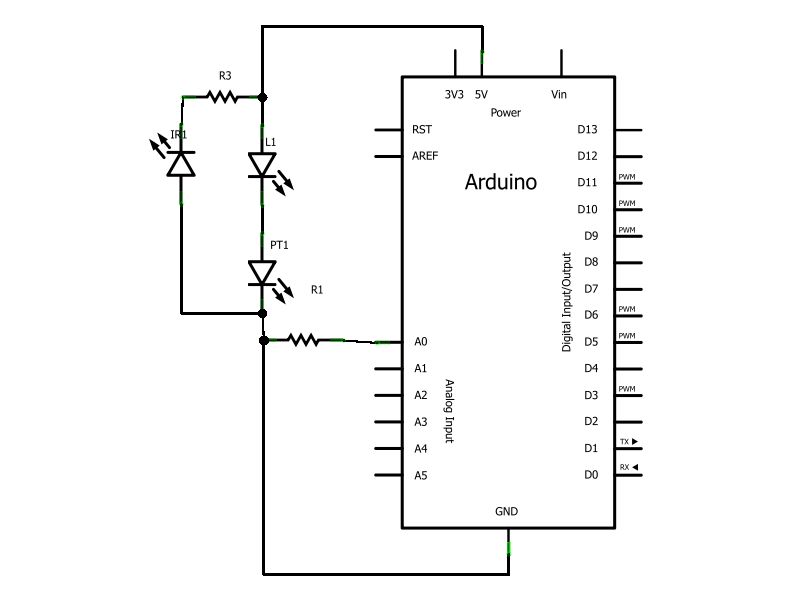
Have you ever wanted to create a line-following robot but found infrared sensors too expensive? If you are located in the UK and have access to a Maplin store nearby, you can purchase infrared transmitters and receivers for just...
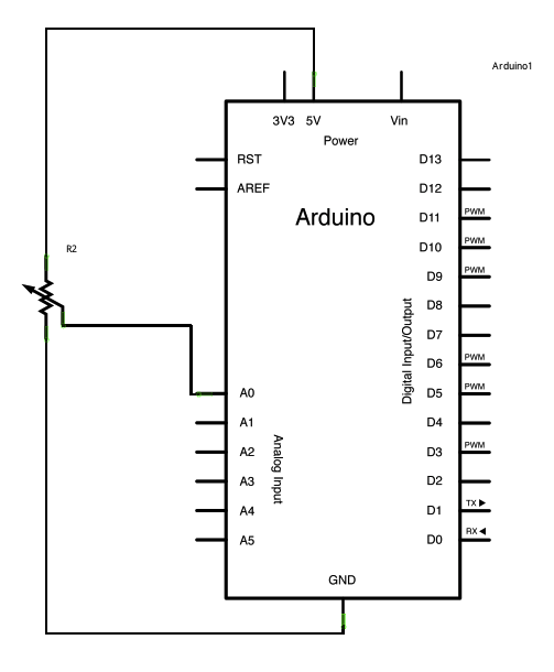
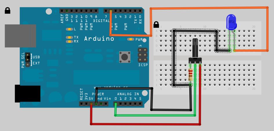
A potentiometer is a simple knob that provides variable resistance, which can be read into the Arduino board as an analog value. In this example, a potentiometer is connected to one of the Arduino's analog inputs to control the...
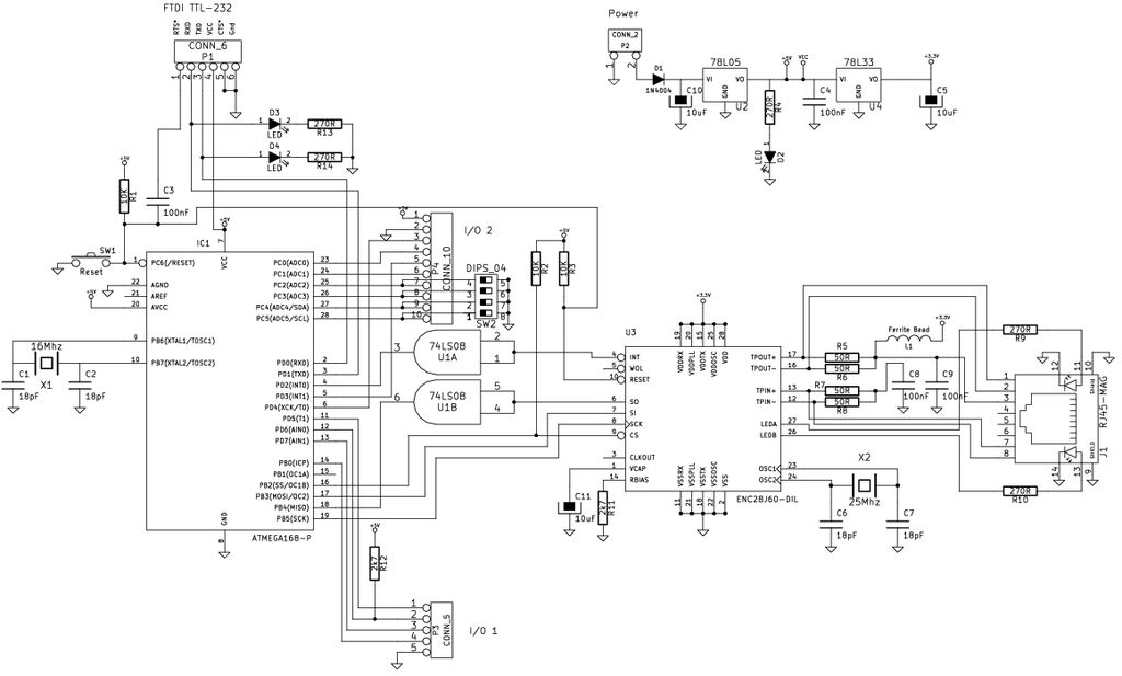
The Arduino is a simple and accessible controller platform suitable for various projects. A few months ago, an Ethernet shield was purchased for it. The Arduino platform is widely recognized for its user-friendly interface and versatility, making it a popular...
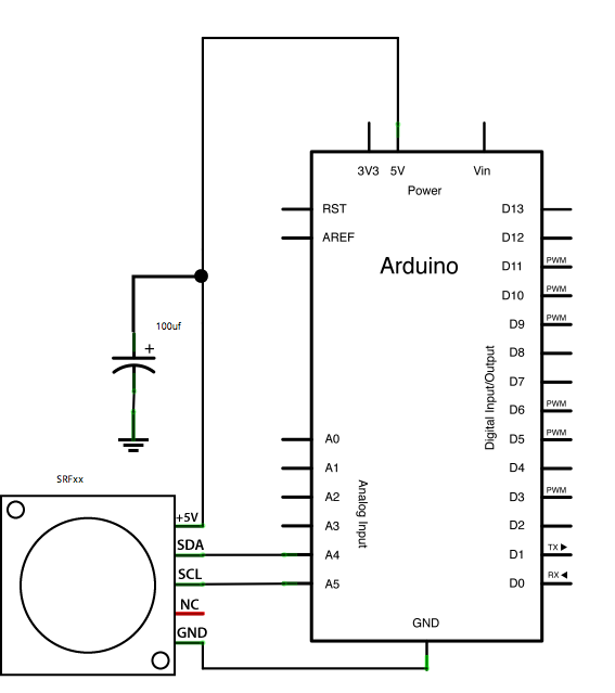
This example demonstrates how to read a Devantech SRFxx, an ultrasonic range finder that communicates via the I2C synchronous serial protocol, using Arduino's Wire Library. The I2C protocol utilizes two wires for data transmission: a serial clock pin (SCL)...
This guide explains how to set up an automated gardening system using an Arduino and other inexpensive electronic components. The system promotes sustainable gardening by utilizing sensors to measure soil moisture and a web scraper to forecast future weather...
The analog to digital sketches have been extensively covered using various components. To progress to more complex circuits and concepts, it is essential to understand these simpler ones. This tutorial will not delve as deeply as others due to...