
Basic FET Amplifier

The FET amplifier circuit operates by utilizing field-effect transistors (FETs) to amplify signals. The FET's gate-source voltage (Vgs) is critical in controlling the conductivity of the channel between the source and drain. When the gate voltage is sufficiently negative compared to the source, it creates an electric field that depletes charge carriers in the channel, thus controlling the drain current (Id).
In the described configuration, the source resistor plays a pivotal role in establishing the biasing conditions. The voltage drop across the source resistor (Vs) is directly proportional to the drain current (Id), which is defined by Ohm's law (Vs = Id * Rs). This feedback mechanism ensures that as the drain current increases, the voltage drop across the source resistor increases, effectively lowering the gate-source voltage and stabilizing the operating point of the amplifier.
The relationship between the gate voltage and drain current elucidates the amplifier's operation: an increase in the input signal (applied to the gate) leads to an increase in drain current, which in turn modifies the drain voltage in an inverse manner. This characteristic enables the FET amplifier to function effectively in various applications, including audio processing.
The inclusion of the JFET switch using the MPF102 allows for versatile circuit configurations, as the symmetrical nature of the JFET permits flexibility in how the circuit can be implemented. The use of an audio mixer highlights the practical application of such circuits in real-world scenarios, where multiple audio signals are combined, maintaining signal integrity through simple addition.
In summary, the FET amplifier circuit demonstrates a fundamental approach to signal amplification, leveraging the unique properties of FETs and associated components to achieve desired electrical characteristics while ensuring stable operation across varying input conditions.This is The Fet Amplifier circuit. This circuit uses FET transistor. The gate of the FET must be negative with respect to the source, so a bias can be achieved in the following manner. The voltage that is across the source resistor is developed by the drain current flowing through the source resistor.
Due to that action, the emitter become positiv e with respect the zero volts rail. Here is the schematic diagram of the circuit: The fet is biased correctly, since the current does not flow at gate make the gate has a zero volts. So, the gate is negative with respect to the source because the source is positive with respect to the gate.
The drain current is controlled by the signal voltage that is applied to the gate. The drain current will be decreased when the signal goes less positive. It will make the drain voltage goes more positive because just a little voltage across the drain resistor. The drain voltage will goes more negative and more voltage across the drain resistor when the drain current is increased because the signal voltage goes more positive.
So, the drain voltage does the opposite of the gate voltage. The silicon controlled rectifier (S. C. R. ) is called as the thyristor. It is like a diode, when the cathode is negative with respect to the anode, the current flowing from cathode to anode. But, the difference of thyristor and diode is Continue reading †’. This is a JFET switch circuit. This circuit uses a MPF102 JFET transistor. In this circuit, the JFET is symmetrical, so the input can be source or drain. The MPF102 is used because this transistor has gate`s reverse breakdown voltage of Continue reading †’.
Audio mixer is used to mix several audio signal from many channel into one channel, in analog form. The basic requirement of an audio mixer is that the mixed signal is a product of simple addition. When connected to several Continue reading †’. Using a FET and two additional transistors (cascaded to improve the gain), a 5V FET voltage regulator can be formed. The additional Tr2 and Tr3 transistors will improve the output current handling and decrease the output impedance.
The output voltage Continue reading †’. Sometimes, in linear equipment design, it`s necessary to take a voltage which is referred to some dc level and generate an amplified output which is referred to ground. Using a differential amplifier similar to that shown in the circuit diagram Continue reading †’. 🔗 External reference
Related Circuits

Useful circuit for self-powered speakers, radios, and TVs; can be used as a car power amplifier. Here is the schematic for an 8-watt audio power amplifier. The described circuit serves as an 8-watt audio power amplifier, suitable for various applications,...
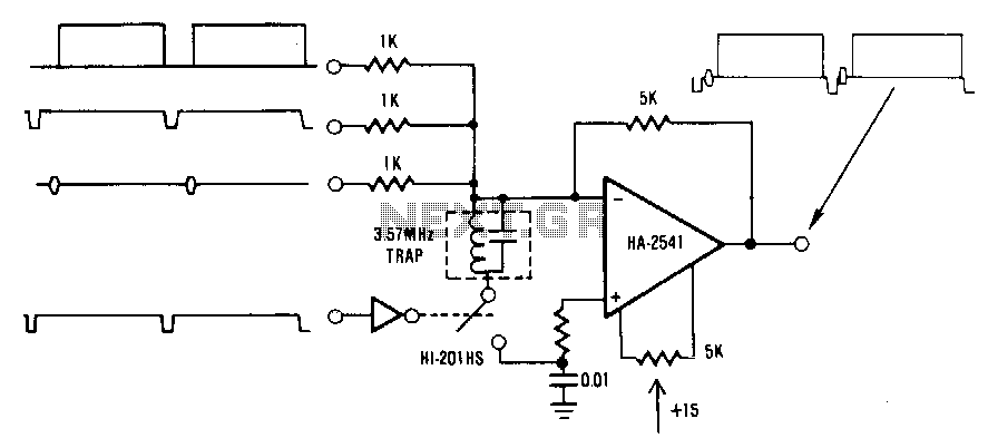
This circuit is a conventional summing amplifier configuration that incorporates a de-clamping circuit. The operation is straightforward; each component—synchronization, color burst, picture information, etc.—of the composite video signal is connected to its respective input terminal of the amplifier. These...
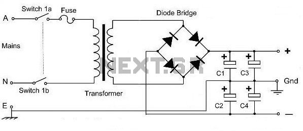
This is a basic dual polarity power supply circuit diagram. It requires the following components: a center-tapped transformer, four diode rectifiers (or one diode bridge), and four electrolytic capacitors. The value of each component is essential for the circuit's...
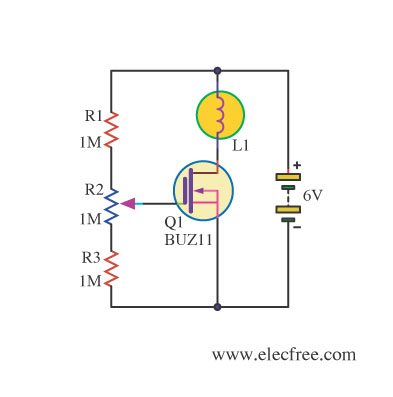
Changing the value of R2 alters the intensity of the lamp in this circuit, demonstrating the utility of a MOSFET as a variable resistor. An N-Channel Power MOSFET, designated as Q1, is utilized in the circuit. The specific part...

This design circuit outlines a simple, low-cost, and ultra-compact VHF/UHF Low-Noise Amplifier (LNA) that can be implemented using the MAX2664 and MAX2665 devices, which are specifically tailored for VHF/UHF applications. The MAX2664 operates within the UHF frequency range of...
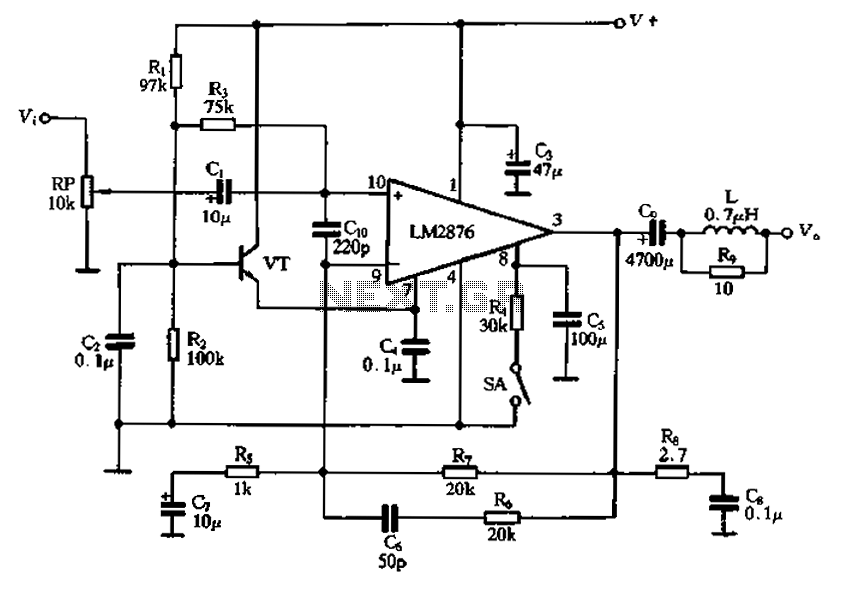
A single power amplifier circuit using the LM2876 IC is designed. An external transistor (VTf) is configured to form an emitter follower, which provides a neutral level (7 feet) for the LM2876, ensuring reliable noise suppression in the circuit...