
Basic Hall Effect Sensor IC
The Hall Effect Sensor operates based on the principle that a voltage is generated across a conductor when it is exposed to a magnetic field perpendicular to the current flow. This phenomenon, known as the Hall Effect, allows for the detection of magnetic fields with high sensitivity and accuracy. Hall Effect Sensors are commonly used in various applications, including automotive systems, industrial automation, and consumer electronics.
The Magnetic Hall Effect Switch, a specific type of Hall Effect Sensor, functions as a binary output device that activates or deactivates based on the presence or absence of a magnetic field. When a magnetic field is applied, the switch closes, allowing current to flow through the circuit. Conversely, when the magnetic field is removed, the switch opens, interrupting the current. This characteristic makes it ideal for applications such as position sensing, speed detection, and contactless switching.
In terms of circuit design, a typical Hall Effect Sensor circuit includes the sensor itself, a power supply, and a load. The sensor is connected to a voltage source, often in the range of 5V to 15V, depending on the specific sensor model. The output can be configured to provide either an analog voltage that varies with the magnetic field strength or a digital output that toggles between high and low states.
To enhance the performance of the Hall Effect Sensor, additional components such as resistors and capacitors may be included in the circuit. Resistors can be used for current limiting and signal conditioning, while capacitors may serve to filter noise and stabilize the output signal. Proper layout and grounding techniques are also crucial to minimize interference and ensure reliable operation.
Overall, the Hall Effect Sensor and Magnetic Hall Effect Switch are essential components in modern electronic systems, providing efficient and reliable methods for magnetic field detection and control.Electronics Tutorial about the Hall Effect Sensor and Magnetic Hall Effect Switch which is an Output Transducer used to detect Magnetic Fields.. 🔗 External reference
Related Circuits
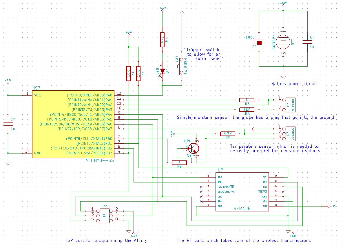
The goal is to create a final package that is as inconspicuous as possible, without any visible wires or adapters. This necessitates powering the project with a small battery. To conserve energy, the ATMega (or potentially the ATTiny) will...
This compact water sensor alarm circuit emits a loud warning sound when a humidity sensor detects the presence of water. The circuit utilizes the low-power comparator LM1801 from National Semiconductor. A fixed reference voltage for the integrated circuit is...
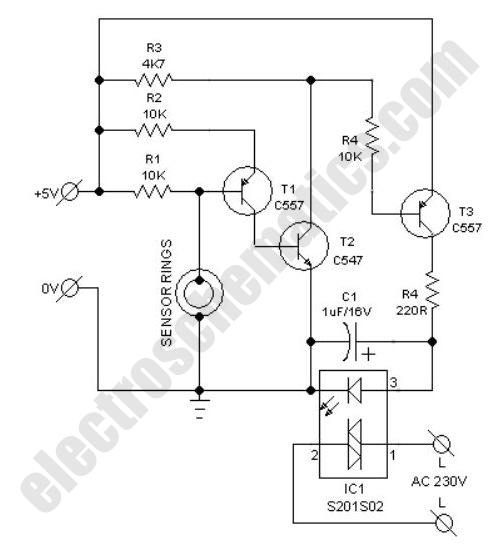
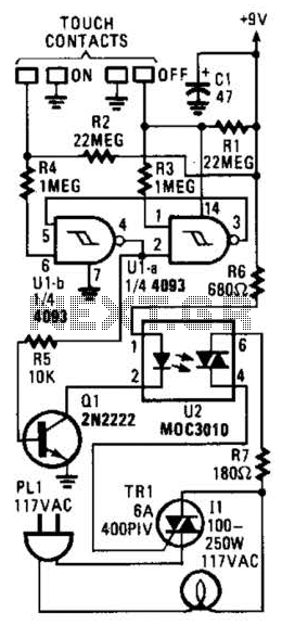
This very simple circuit acts as a high sensitivity capacitive sensor. Lamps and/or Buzzers are operated at half the mains supply voltage when a part of the human body comes in contact with the sensor or approaches it at...
The following circuit illustrates a BC 547 transistor used in a garage alarm sensor circuit diagram. Features include a simple single-zone burglar alarm circuit. The BC 547 transistor is a popular NPN bipolar junction transistor (BJT) that is frequently used...
This device transmits data regarding the state of an office to Twitter, as it is deemed slightly more relevant than sharing similar information about a residence. It holds potential significance for biodiversity-related activities, especially when integrated with long-range WiFi...
In this circuit, two 567 tone decoders are utilized. One functions as an oscillator, while the other acts as a detector. Connecting TP1 and TP2 allows U2 to receive the signal from U1, resulting in pin 8 of U2...