
Battery Powered Electret Microphone Pre-Amplifier
The electret microphone pre-amplifier circuit is designed to amplify the weak audio signals generated by an electret microphone. The LMV721 op-amp serves as the core amplification component due to its favorable specifications, including low noise operation and minimal power consumption, making it suitable for battery-powered applications.
The circuit typically includes the electret microphone, which contains a built-in FET that converts sound waves into electrical signals. The output from the microphone is connected to the non-inverting input of the LMV721. A resistor-capacitor (RC) network may be employed to filter out high-frequency noise and stabilize the gain. The gain of the amplifier can be adjusted by selecting appropriate feedback and input resistors.
Power supply considerations are critical; the LMV721 can operate with a single supply voltage, which simplifies the design. Bypass capacitors are recommended close to the power supply pins of the op-amp to reduce power supply noise. The output of the LMV721 can then be interfaced with further audio processing stages or directly with an analog-to-digital converter (ADC) for digital audio applications.
Overall, this schematic provides an efficient solution for amplifying audio signals in various applications, including voice recognition systems, portable audio devices, and other low-power audio applications.Here is a schematic diagram of electret microphone pre-amplifier using LMV721 op-amp. because the LMV721 has low noise and low power features, it would be an. 🔗 External reference
Related Circuits
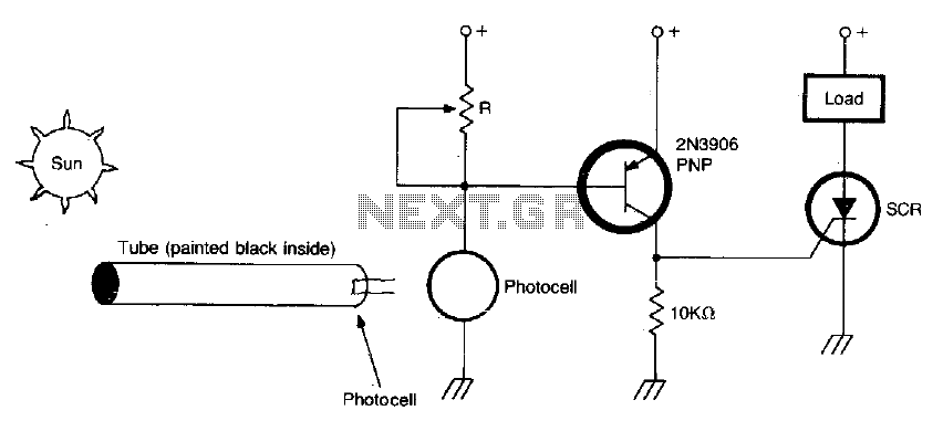
The circuit activates when light, specifically sunlight, strikes the photocell. A potentiometer, labeled R, adjusts the light level at which the alarm is triggered. Additionally, a painted tube, with a black interior, can be utilized on the photocell to...
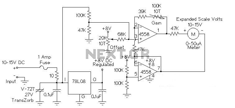
This circuit is used to measure the voltage on a 12V (nominal) lead acid rechargeable battery system. It was specifically designed for use in solar powered systems, but is general enough that it can be used for automotive or...
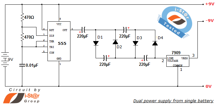
How to create a dual power supply unit using a single battery for laboratory purposes. Dual voltage power supplies are particularly needed for operational amplifier experiments and some instrumentation amplifiers. Additionally, certain low-power audio preamplifiers also require dual voltage...
A simple NiCd charger can be constructed using commonly available components and an inexpensive LM317 or 78xx voltage regulator. The design incorporates a current limiter composed of resistor R3 and a transistor, allowing it to charge multiple cells until...
Application note on designing linear and switch-mode (switching DC-DC converter current source) battery charger applications that require external microcontrollers and related system-level issues for notebook computers. The application note provides guidance on the design of both linear and switching DC-DC...
When the door is opened, SW1 closes, powering the circuit and turning on the lamp. C1 begins to charge slowly through R1, and when the voltage at pins #2 and #6 of IC1 reaches 2/3 of the supply voltage,...