
nicd battery charger
The operation of the circuit is straightforward. If the cells are not fully charged, the charging current flows freely from the voltage regulator, limited by resistor R3 and transistor T1. The maximum charging current, Imax, is determined by the formula Imax = (0.6 V) / R3. For a maximum current of 200 mA, the required value for R3 is 3 ohms. An LED indicates when current limiting is in effect, signaling that the cells are still charging. The voltage on the reference lead of the voltage regulator increases by approximately 2.9 V due to the voltage across the LED, necessitating a minimum number of cells for proper operation. For an LM317, the voltage between the reference lead and the output is 1.25 V, which means at least three cells must be charged (3 * 1.45 V > 2.9 V + 1.25 V). For a 78xx regulator with a voltage drop of around 3 V (plus 2.9 V), a minimum of four cells is required.
As the cells approach full charge, the current gradually decreases, deactivating the current limiter and turning off the LED. At this point, the voltage on the reference lead of the regulator is determined solely by the voltage divider formed by resistors R1 and R2. For a 7805 regulator, R2 is selected to allow a current of 6 mA through it. Combined with the regulator's current draw of about 4 mA, this results in approximately 10 mA flowing through R1. If the voltage across R1 is 4 V (from a 9 V supply down to 5 V), R1 is calculated to be 390 ohms. Consequently, the end-of-charge voltage can be set to approximately 8.9 V. Since the current through the regulator can vary based on the manufacturer and load conditions, R1 may need to be adjusted accordingly. The storage capacitor's value must also correspond to the selected charging current; it can be omitted for pulse charging applications.
The schematic for the NiCd charger typically includes the LM317 or 78xx voltage regulator, resistors R1 and R2 for the voltage divider, resistor R3 for current limiting, and transistor T1 to control the charging current. The LED serves as a visual indicator of the charging status. The configuration allows for flexible charging of NiCd cells while ensuring the safety and longevity of the battery cells through proper current regulation and voltage monitoring.A simple NiCd charger can be built using junk box` components and an inexpensive LM317 or 78xx voltage regulator. Using a current limiter composed of R3 and a transistor, it can charge as many cells as desired until a fully charged` voltage determined by the voltage regulator is reached, and it indicates whether it is charging or has reached the f
ully charged state. If the storage capacitor (C1) is omitted, pulsed charging takes place. In this mode, a higher charging current can be used, with all of the control characteristics remaining the same. The operation of the circuit is quite simple. If the cells are not fully charged, a charging current flows freely from the voltage regulator, although it is limited by resistor R3 and transistor T1.
The limit is set by the formula Imax ‰ (0. 6 V) G· R3 For Imax = 200 mA, this yields R3 = 3 . The LED is on if current limiting is active, which also means that the cells are not yet fully charged. The potential on the reference lead of the voltage regulator is raised by approximately 2. 9 V due to the voltage across the LED. This leads to a requirement for a certain minimum number of cells. For an LM317, the voltage between the reference lead and the output is 1. 25 V, which means at least three cells must be charged (3 G— 1. 45 V > 2. 9 V + 1. 25 V). For a 78xx with a voltage drop of around 3 V (plus 2. 9 V), the minimum number is four cells. When the cells are almost fully charged, the current gradually drops, so the current limiter becomes inactive and the LED goes out.
In this state, the voltage on the reference lead of the regulator depends only on voltage divider R1/R2. For a 7805 regulator, the value of R2 is selected such that the current through it is 6 mA. Together with the current through the regulator (around 4 mA), this yields a current of around 10 mA through R1.
If the voltage across R1 is 4 V (9 V 5 V), this yields a value of 390 . The end-of-charge voltage can thus be set to approximately 8. 9 V. As the current through the regulator depends on the device manufacturer and the load, the value of R1 must be adjusted as necessary. The value of the storage capacitor must be matched to the selected charging current. As already mentioned, it can also be omitted for pulse charging. 🔗 External reference
Related Circuits
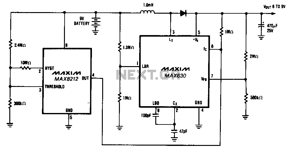
The circuit provides a minimum output of 7 V until the 9-V battery voltage drops below 2 V. When the battery voltage is above 7 V, the MAX630's IC pin is low, placing it in shutdown mode, which consumes...
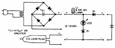
NiCd charger with current and voltage limiting power supply. This is a car NiCd battery charger circuit that can charge any Ni-Cd battery between 4.8 and 4.4 volts from a classic 12 volts car battery. The charging current can...
The circuit was constructed on a Vero board and tested with a large electrolytic capacitor in place of a battery. A 500-ohm preset resistor determines the output voltage, while a 47k preset resistor regulates the hysteresis and establishes the...
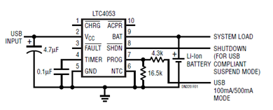
The schematic presented illustrates a minimal component solution for a USB battery charger utilizing the LTC4053 integrated circuit (IC) to create a fully compliant USB charger. This IC functions as a standalone linear charger designed for lithium-ion (Li-ion) batteries,...
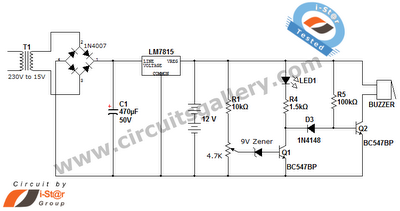
This is a straightforward 12V rechargeable smart battery charger circuit. It can be utilized as a charger for car batteries, inverter batteries, emergency light batteries, and more. An automatic indicator alarm circuit accompanies this battery charger schematic. The primary...

The short in a Ni-Cad battery can be "burned off" with this zapper. The use of the SCR prevents heavy discharge current from damaging the switch contacts. More: follow the diagram. This circuit utilizes a zapper to eliminate shorts in...