
Common ground for different voltages in relay circuit
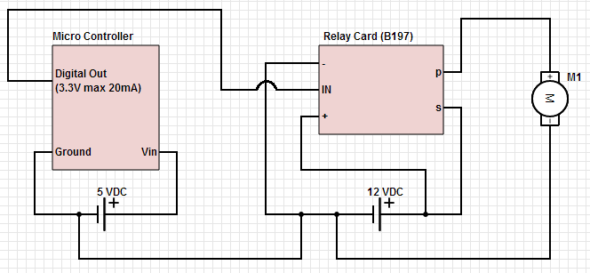
To achieve the control of a 12 VDC device using a microcontroller and a relay card, a circuit design must incorporate several key components. The microcontroller, which serves as the control unit, will send a signal to activate or deactivate the relay. The relay acts as an electrically operated switch that can handle the higher voltage and current needed to power the 12 VDC device.
The circuit typically consists of the following components:
1. **Microcontroller**: This device generates the control signal. Common choices include Arduino, PIC, or STM32 microcontrollers. The microcontroller's output pin is connected to the relay module's input pin.
2. **Relay Module**: The relay module consists of one or more relays capable of handling the 12 VDC load. It usually includes an opto-isolator for safety and to protect the microcontroller from back EMF generated by the relay coil. The relay coil requires a 12 VDC supply for operation, which can be provided from the same power source as the device being controlled or from a separate regulated power supply.
3. **Power Supply**: A 12 VDC power supply is necessary to power both the relay and the connected device. This power supply should be capable of providing sufficient current to meet the demands of the device being controlled.
4. **Protection Diode**: A flyback diode should be placed across the relay coil terminals to prevent voltage spikes (back EMF) when the relay is deactivated. This diode ensures that the current generated by the collapsing magnetic field does not damage the microcontroller.
5. **Control Circuit**: The microcontroller's output pin is connected to the input of the relay module, which may include a transistor to amplify the control signal. When the microcontroller sends a high signal, the transistor turns on, energizing the relay coil and closing the switch, allowing current to flow to the 12 VDC device.
6. **Load**: The 12 VDC device that needs to be controlled. When the relay is activated, the device receives power and operates as intended.
The circuit can be designed on a breadboard for prototyping or laid out on a printed circuit board (PCB) for a more permanent solution. Proper attention should be given to the layout to minimize noise and interference, especially if the microcontroller operates at lower voltages. Additionally, the relay's specifications should match the requirements of the load to ensure reliable operation.
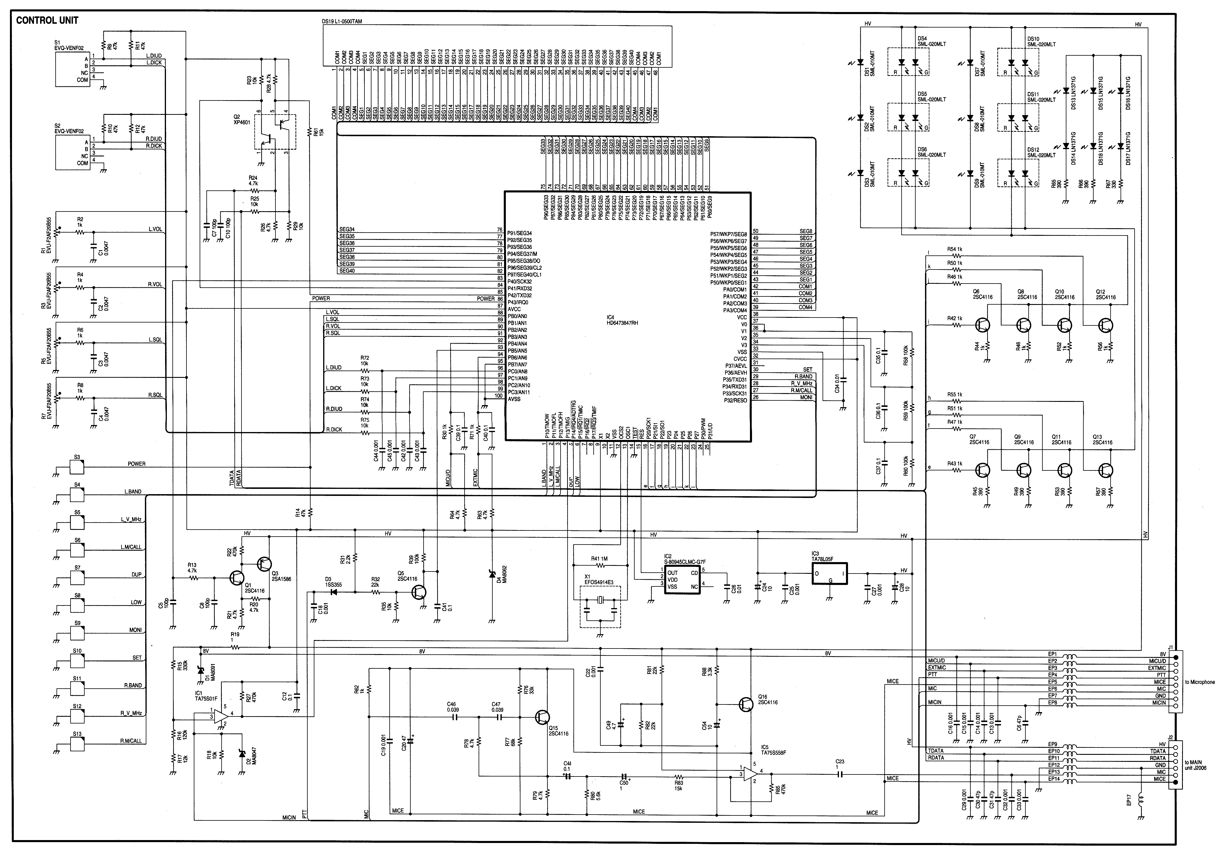
In conclusion, this setup allows for effective control of a 12 VDC device using a microcontroller through a relay, enabling automation and remote control capabilities in various applications.Hello, My goal is to control a 12 VDC device (on/off) from a microcontroller using a relay card. The relay needs 12 VDC operating power (I use the.. 🔗 External reference
Related Circuits
Individuals seeking a distinctive gift for Christmas and New Year may find this project appealing. Certification of this project will undoubtedly create a preference for it. The project in question appears to be a creative endeavor aimed at providing a...
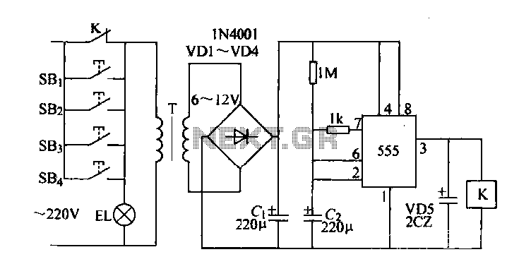
Control buttons SB1 to SB4 can be installed in various positions within a corridor. By pressing any one of these buttons, the EL horse lights will turn on. After releasing the button, the transformer and rectifier supply power to...

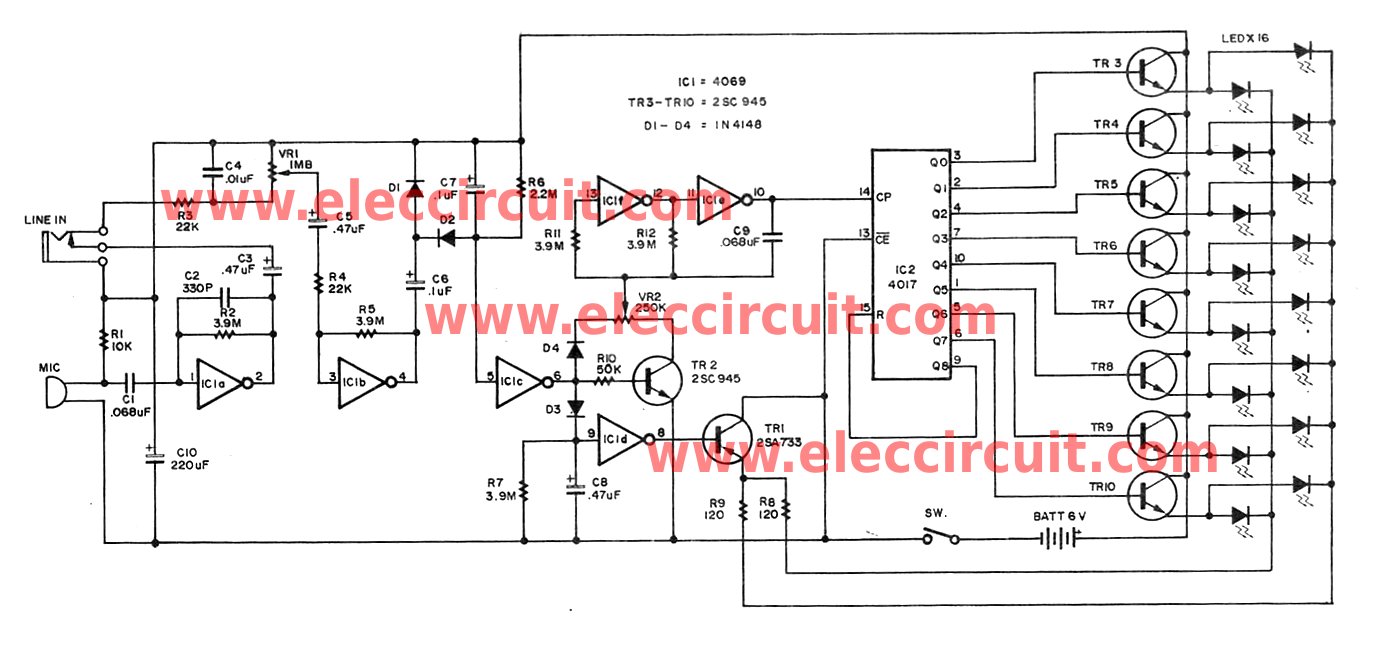
Controlling the speed of a three-phase AC motor is achieved by regulating the frequency of the power supply, as the motor operates in synchronization with the line frequency. A three-phase AC motor speed controller functions as a three-phase sine...
The circuit is a bell timer. This project utilizes the AT89S52 microcontroller and an I2C EEPROM for storing alarm timings. Additionally, the 7-segment display has been replaced with an LCD display. The DS1307 is employed for real-time clock functionality....
This device is a combination digital clock timer and solar panel charge controller designed to maintain a deep cycle battery from a solar panel. The timer output controls a 12-volt load for a 32-minute interval each day. The start...
Radio Control Circuits PDF Manual Download. This document serves as a comprehensive guide to radio control circuits, intended for individuals seeking to understand the principles and applications of radio frequency (RF) technology in controlling various devices. The manual covers fundamental...