Dark detector circuit using LDR LED
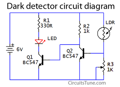
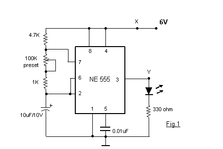
This is a basic dark detector or sensor circuit diagram based on a photoresistor (LDR) and a few components.
The dark detector circuit utilizes a photoresistor (LDR) as the primary sensing element. The LDR is a light-dependent resistor that changes its resistance based on the intensity of light falling on it. In low-light conditions, the resistance of the LDR increases significantly, allowing the circuit to detect darkness.
The circuit typically comprises a few key components: the LDR, a resistor, a transistor, and an LED or buzzer for output indication. The LDR is connected in a voltage divider configuration with a fixed resistor. As ambient light decreases, the voltage across the LDR increases, which can be fed into the base of a transistor.
When the voltage at the base of the transistor exceeds a certain threshold, the transistor turns on, allowing current to flow from the collector to the emitter. This current can then energize an output device such as an LED or a buzzer, providing a visual or audible indication of low light conditions.
To enhance the circuit's functionality, additional components such as a potentiometer may be included to adjust the sensitivity of the LDR, allowing for tuning based on the specific application or environment. Furthermore, a capacitor can be added in parallel with the output device to create a delay in response time, preventing rapid on-off cycles in fluctuating light conditions.
Overall, this dark detector circuit serves as a fundamental example of using an LDR in electronic applications, showcasing the principles of light sensing and transistor switching in a straightforward design.This is a basic dark detector/sensor circuit diagram based on a Photo Resistor (LDR) and few numbers of parts.. 🔗 External reference

