
Dc motor speed controller circuit using NE555
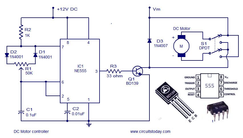
The described circuit utilizes the NE555 timer IC in astable or monostable mode to control the speed and direction of a DC motor. In the astable configuration, the NE555 generates a PWM (Pulse Width Modulation) signal, which is used to vary the average voltage supplied to the motor, thereby controlling its speed. The duty cycle of the PWM signal can be adjusted by changing the resistance and capacitance in the timing network connected to the NE555.
For direction control, an H-bridge configuration is often employed. This arrangement allows the current to flow through the motor in either direction, enabling forward and reverse operation. The control signals for the H-bridge can be derived from the outputs of the NE555 timer or from additional control circuitry, such as a microcontroller or manual switches.
Key components of the circuit include the NE555 timer, resistors, capacitors, an H-bridge driver (such as the L298 or L293D), and the DC motor itself. Proper selection of component values is crucial for achieving the desired speed range and responsiveness of the motor control. Additionally, protective elements like diodes may be included to prevent back EMF from damaging the circuit when the motor is turned off.
Overall, this DC motor controller circuit provides a flexible solution for controlling the speed and direction of a DC motor, suitable for various applications in robotics, automation, and hobby projects.A DC motor controller based on NE555 timer is shown here. Direction of rotation of DC motor can be also changed by this DC motor speed control circuit.. 🔗 External reference
Related Circuits
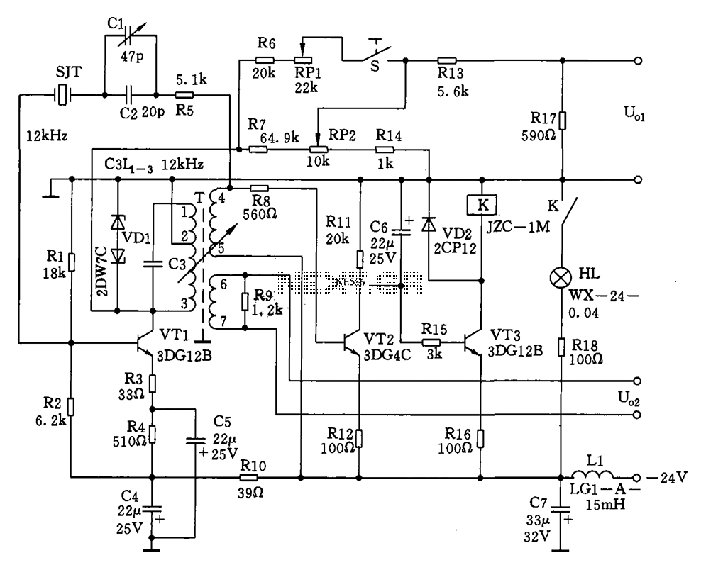
The circuit features a 12kHz intermediate frequency (IF) oscillator utilizing a quartz crystal for precision frequency generation. It includes components for output level adjustment, a level-up circuit, and an alarm circuit. The design employs a unique single-tuned variable feedback...
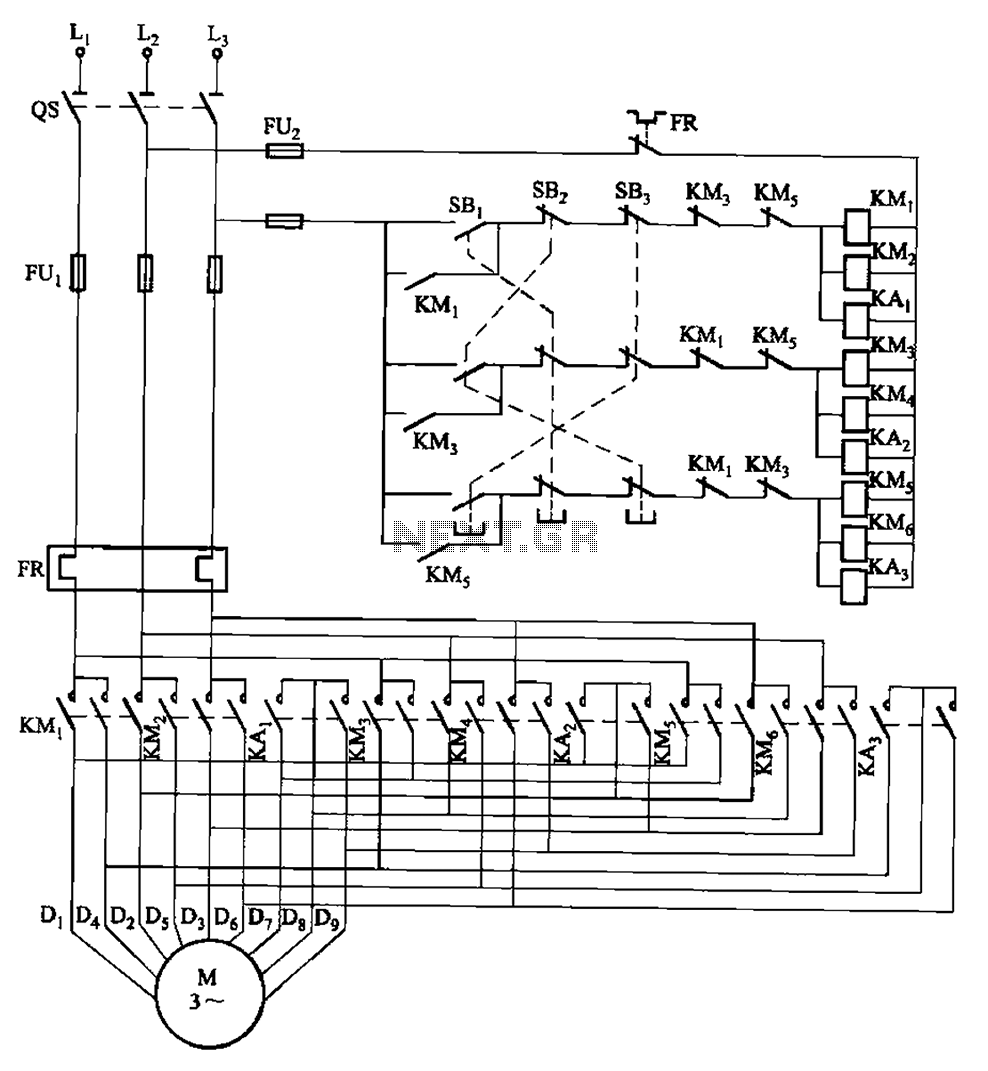
The circuit depicted in Figure 3-115 utilizes contactors and double buttons, allowing for speed conversion without the need to press the stop button. The buttons SBi, SBz, and SB3 correspond to high, medium, and low-speed operation, respectively. This circuit design...
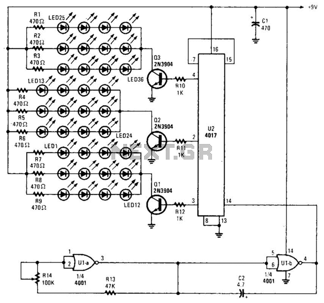
Originally designed as a three-bell animation circuit for Christmas decorations, this circuit can also be utilized for various other applications that require a flashing effect. By reconfiguring U2 (refer to the data manual), it is possible to achieve more...
The basic two-transistor flasher has become widely utilized in various applications due to its simplicity and versatility. It has been employed in circuits such as a micropower low battery indicator, a lightning detector, an off-line switching power supply, a...
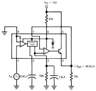
The LM2917 IC chip is specifically designed as a Frequency to Voltage Converter. It requires only a few external components for its operation. The datasheet for the LM2917 IC includes several application examples of the Frequency to Voltage Converter....
A basic circuit of the 89C2051 shown here can be made easily using point-to-point soldering with a universal PCB. Use an ordinary 20-pin socket, do not use a circle-pin socket. D1 is a small dot LED. U2 can be...