Digital Encoder Circuit diagram Using Stepper Motor
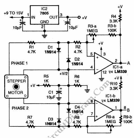
The circuit illustrated in the schematic diagram below allows for the visualization of the direction and shaft rotation of a stepper motor on an LED display. Instead of utilizing a digital rotation encoder as an input, this circuit employs a stepper motor. The schematic diagram of the circuit is provided below.
The described circuit integrates a stepper motor with an LED display to provide real-time feedback on the motor's rotational direction and position. The stepper motor operates through a series of discrete steps, allowing for precise control of its rotation. In this configuration, the motor's rotation is monitored by a microcontroller, which interprets the signals from the motor and translates them into visual information displayed on the LED screen.
The schematic typically includes the stepper motor, a microcontroller (such as an Arduino or similar device), and the LED display. The microcontroller is programmed to control the stepper motor's operation, sending pulse signals to the motor driver, which in turn energizes the motor coils in a specific sequence. This sequential energization causes the motor to rotate in defined steps, either clockwise or counterclockwise.
The LED display is interfaced with the microcontroller to show the current position of the motor shaft. The display can represent the rotation direction with indicators such as arrows or numerical values indicating degrees of rotation. The circuit may also include additional components such as resistors, capacitors, and possibly a power supply to ensure stable operation.
In summary, this circuit is an effective solution for applications requiring precise motor control and visual feedback, allowing users to monitor and adjust the motor's performance in real-time. The schematic diagram serves as a crucial reference for understanding the connections and components involved in the setup.Using circuit depicted in the schematic diagram below, the direction and shaft rotation of stepper motor can be seen on the LED display. Alternative to digital rotation encoder as a digital encoder input, this circuit uses a stepper motor.
Here is the schematic diagram of the circuit:.. 🔗 External reference
