
Double IC For Circuit an Infrared Toy Car Motor Controller
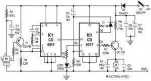
The Infrared Toy Car Motor Controller circuit utilizes the 4047 and 4017 ICs to manage the operation of the toy car motors effectively. The 4047 is configured in astable mode to generate a square wave output, which serves as a clock signal for the 4017 decade counter. The 4017 is responsible for sequentially activating the outputs that control the motors, allowing for forward and reverse motion as well as turning.
The circuit features a 16V capacitor that provides stability and filtering for the power supply, ensuring that the ICs operate reliably. A 100k resistor is incorporated in the timing circuit of the 4047 to set the frequency of the output signal. The use of dual ICs enhances the functionality of the circuit, allowing for more complex control over the motors.
Additional components include diodes that protect the circuit from back EMF generated by the motors, LEDs that provide visual feedback on the circuit's operation, and transistors that amplify the control signals to drive the motors effectively. The switch allows the user to turn the circuit on and off, providing simple user interaction.
Overall, this circuit design demonstrates a practical application of basic electronics principles, integrating various components to create a functional motor controller for an infrared toy car. The combination of the 4047 and 4017 ICs, along with the supporting components, results in a robust solution for controlling motor functions in toy applications.The following circuit shows about Circuit an Infrared Toy Car Motor Controller. This circuit based on the 4047 and4017 IC. Features: 16V Capacitor, 100k Resistor, Double IC. Component: IC, Switch, Diode, LED, Resistor, Capacitor, Motor, Transistor. [diychamber. com] Tags: Capacitor, circuit diagram, control circuit, control diagram, co ntrol schematic, Diode, electronic circuit, electronic control, IC, LED, Motor, Resistor, schematic diagram, switch, Transistor 🔗 External reference
Related Circuits
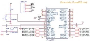
This is the circuit diagram of a line follower/line tracker robot. The circuit is derived from tutorial documentation, which can be downloaded at the end of this article. The line follower robot utilizes eight proximity sensor modules. Each sensor...
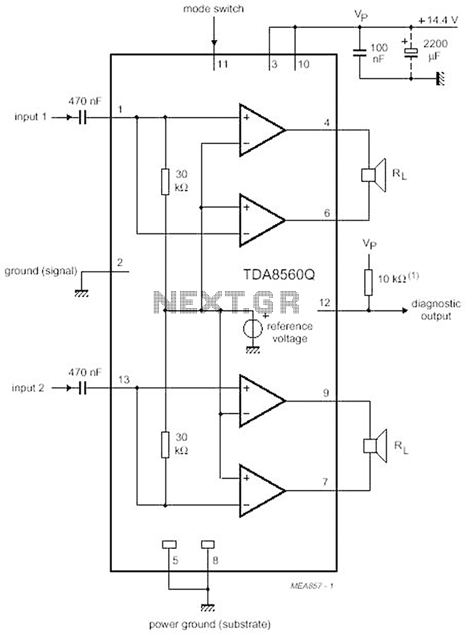
The proposed scheme is straightforward, requiring only a few external electronic components, making it suitable for car audio construction. The output power ranges from 2 to 4 Ohms, providing 2 x 30 W (with a maximum of 2 x...
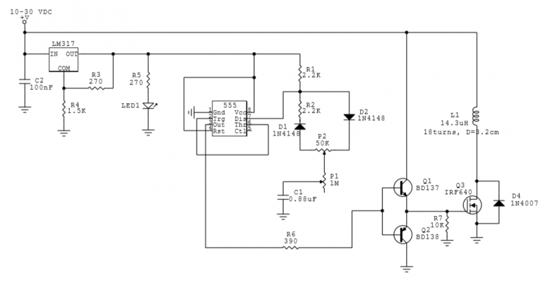
This circuit utilizes a 555 Integrated Circuit (IC) to generate a pulsed magnetic field, which can be employed for pulsed electromagnetic field (PEMF) therapy. The human body is affected by natural magnetic fields, including the Earth's magnetic field, geomagnetic...
Here is a simple project that sends continuous or switch controller MIDI messages that correspond to the position of a potentiometer. Given a few parts and a cannibalized volume or wah-wah pedal, you can build this MIDI controller pedal...
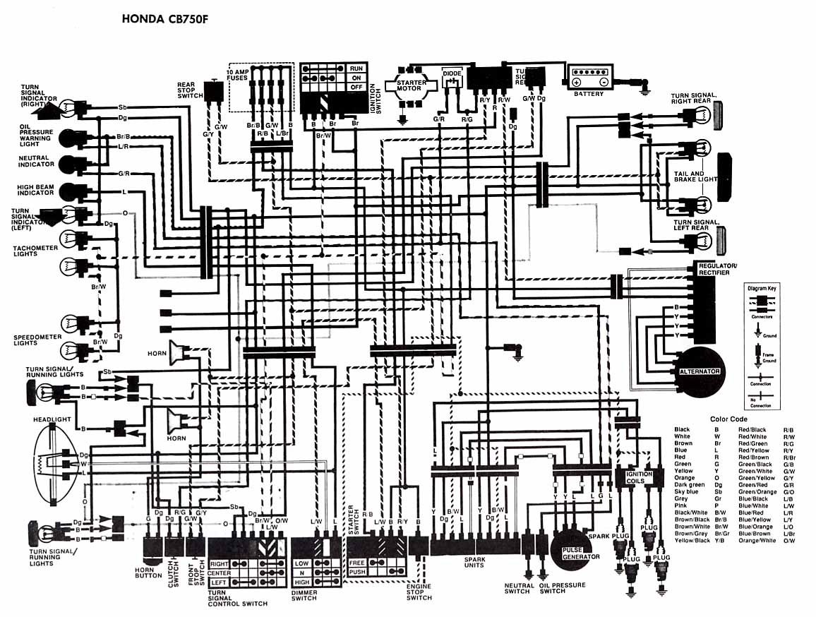
The following account presents the electrical wiring diagram for the Honda Motorcycle CB750F. It illustrates the connections between various Honda components, including the right turn signal indicator light, oil pressure warning light, neutral indicator, high beam indicator, turn signal...
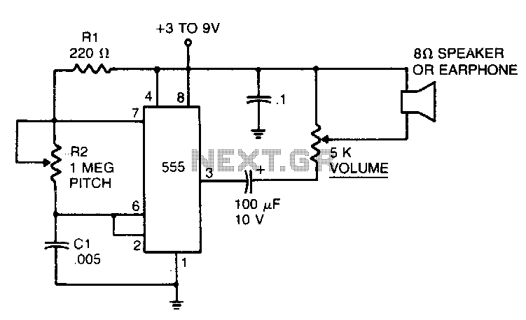
In the 555 oscillator circuit, adjusting R2 will provide output frequencies ranging from below 200 Hz to above 62 kHz. It is recommended to use a good quality miniature speaker to produce frequencies around 20 kHz. The 555 oscillator circuit...