
Dual Input-Combining Stereo Line Amplifier

This circuit employs a combining amplifier to facilitate the merging of audio signals from two distinct sources, specifically designed for scenarios where manual switching of audio inputs is impractical. The design incorporates two stereo inputs: one from the TV's audio output and the other from the DVD player's audio output, ensuring seamless integration without audio conflicts.
The combining amplifier is configured to maintain a consistent voltage gain of 1.5, allowing for a slight amplification of the audio signals while preserving the integrity of the original sound. The gain can be adjusted by replacing the two 15 kΩ resistors with resistors of different values, providing flexibility in audio output levels based on user requirements or the specific characteristics of the connected audio devices.
The input impedance of the circuit is set at 10 kΩ, which is compatible with standard line-level audio outputs, ensuring minimal loading on the audio sources. To prevent potential issues with cable capacitance or amplifier input capacitance affecting the audio quality, 47 Ω series resistors are incorporated at the output stage. This isolation helps to maintain signal integrity and reduce the risk of distortion.
Powering the circuit is straightforward, as it utilizes a regulated 12V DC power supply. This design choice ensures stable operation and minimizes the risk of noise and interference from the power source, which is crucial in maintaining high-quality audio performance.
Overall, this circuit represents an effective solution for combining audio signals from multiple sources, providing convenience and enhanced audio reproduction capabilities in home entertainment setups.This circuit takes two separate line-level stereo (L & R) signals and combines them into one stereo (L & R) output, thus avoiding the need to switch between two pairs of input signals. In the author`s application, it is used to feed the stereo audio from a TV receiver and a DVD player into an external amplifier.
The need for the circuit arose beca use of a design peculiarity in the TV receiver. The TV has four A/V inputs and one A/V output. AV1-AV3 accept composite or S-video plus stereo audio inputs and these feed into the TV`s A/V output. AV4 accepts Component video (Y/Pb/Pr) plus stereo audio but unlike AV1-AV3, its audio (and video) signals are not fed to the TV A/V output.
The Y/Pb/Pr input was chosen for use with the DVD player because of its superior video quality, while the audio was to be fed to an external amplifier for improved reproduction. However, manual switching was inconvenient, hence the genesis of this design. In use, the DVD player audio is fed in parallel to TV AV4 and to one input pair of the combining amplifier, while the TV audio output feeds the other input pair.
The amplifier output goes to the external audio amplifier. There is no conflict between the two audio inputs because when AV4 (DVD player) is selected, there is no TV audio output. In all other modes, the DVD player is off. As shown, the circuit has a voltage gain of 1. 5 times (3. 5dB) but this can be altered as required by changing the two 15kW resistors. Input impedance is 10kW and the outputs are isolated from cable and amplifier input capacitance with 47W series resistors.
The circuit can be powered from a regulated 12V DC plugpack. 🔗 External reference
Related Circuits
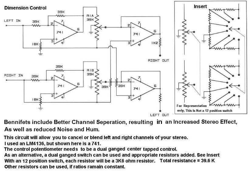
The circuit includes better channel separation, resulting in an increased stereo effect, as well as reduced noise and hum. This schematic will allow you to cancel or blend left and right channels of your stereo. Uses the LM4136 but...
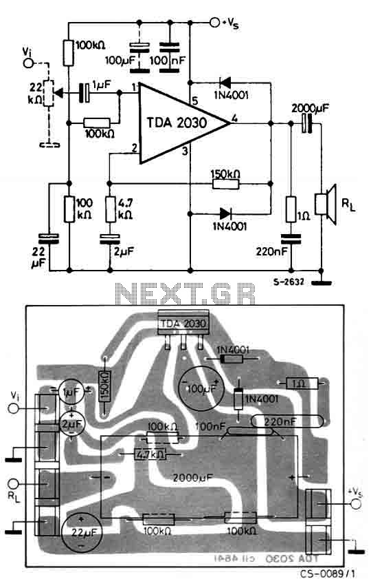
The circuit utilizes the TDA2030, a monolithic integrated circuit housed in a Pentawatt package, designed for use as a low-frequency class AB amplifier. It typically delivers 14W of output power (with a distortion factor of 0.5%) at 14V with...
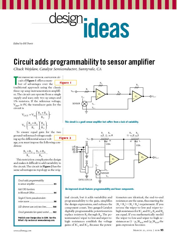
This tutorial provides information related to sensor amplifiers, schematics, and noise. It presents a discussion around sensors and their outputs. Sensor amplifiers are critical components in various electronic systems, especially in applications where signals from sensors need to be conditioned...

The circuit is a high-power car audio amplifier schematic. It functions as a car audio amplifier using the PA02 and LH0101 integrated circuits (ICs). Each IC delivers an output power of 30W with an 8-ohm impedance. The part list...
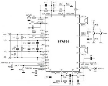
This is a stereo amplifier circuit diagram. The amplifier will produce stereo output channels with a power audio output that can reach up to 70W for each channel. The amplifier is built using the STA550 chip from STMicroelectronics. It...
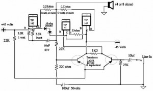
A 150W power amplifier circuit diagram utilizing power transistors TIP41, TIP142, and TIP147. The design is straightforward enough to construct without a printed circuit board (PCB). The power output range is approximately 100-150W. The 150W power amplifier circuit is designed...