
Electronic Circuit Schematic DC Motor Driver using L293D Dual H-Bridge
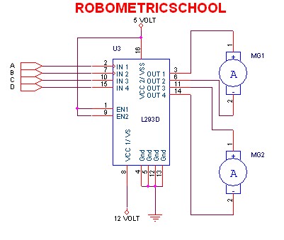
According to the guidance provided in Figure 3, the motor will rotate clockwise when a logic high (1) is applied to input A and a logic low (0) is applied to input B. Conversely, the motor will rotate counterclockwise when input A receives a logic low (0) and input B is set to a logic high (1). To stop all motors, a logic high (1) must be applied to all input pins. It is crucial to avoid applying a logic low (0) to all inputs simultaneously, as this can lead to errors or damage to the L293D, potentially resulting in overheating or short circuits.
The L293D is a dual H-bridge motor driver capable of controlling the direction and speed of DC motors. Each H-bridge can control one motor, allowing for independent operation of two motors. The device features built-in diodes for back EMF protection, which is essential for safeguarding the circuit from voltage spikes generated by the motors during operation.
To implement the circuit, the L293D is connected to the power supply, motors, and a microcontroller or other control logic. The control signals from the microcontroller dictate the state of the inputs A and B for each motor. By using PWM (Pulse Width Modulation) on the enable pins of the L293D, speed control can also be achieved, allowing for variable motor speeds in addition to directional control.
Proper heat dissipation measures should be considered, as the L293D can generate heat during operation, especially under high load conditions. Heat sinks may be necessary to maintain optimal operating temperatures and prevent thermal shutdown. Overall, the L293D motor driver is a versatile component for robotics and automation applications, providing efficient control of DC motors in various configurations.According electronic schematic of DC driver motor using L293D in figure 2, we can use it to control two DC motor continuously. We can control DC motor one to rotate clock wise and DC motor two to rotate anti clock wise. We also can control all motor to rotate clock wise, anti click wise, or stop all. We can control it with give control in input of L293D. You can use guidance like in figure 3 bellow: From figure 3 above, we can make motor rotate clock wise when in input we give 1 logic in A and 0 logic in B. Also we can make motor rotate anti clock wise when input we give 0 logic in A and 1 logic in B. We can stop all motor with give in all input 1 logic. Attention you don`t give in all input with 0 logic, because it can make L293D error or damage like burn or shot circuit.
So careful when you set it. Thank you very much for your visiting in Robometricschool blog, We hope you will get more information about Robotic, Mechatronic, and Electronic. And don`t forget to give us your comment about this article. Let keep for building comment. 🔗 External reference
Related Circuits
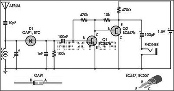
This circuit is an amplified crystal set. The inductor can be a standard AM radio ferrite rod antenna, while the tuning capacitor is a variable plastic dielectric gang designed for small AM radios. The aerial tuned circuit feeds diode...
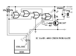
The circuit consists of a 555 timer IC configured as a multivibrator, which operates with two probes to measure the water level. When the capacitance between the probes indicates a high water level, the output from the 555 timer...
A DIY GSM jammer schematic diagram designed specifically for GSM1900 frequencies ranging from 1930 MHz to 1990 MHz. The GSM1900 mobile phone network is utilized in the USA, Canada, and most South American countries. This cell phone jammer is...
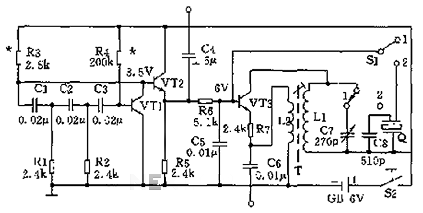
The high-frequency signal generator is designed to produce a low frequency of 1 kHz, an intermediate frequency (IF) signal of 465 kHz, and high frequencies ranging from 525 kHz to 1605 kHz. This device is particularly useful for radio...
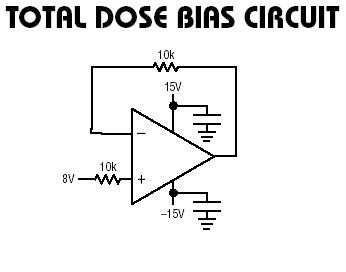
The RH1078M is a micropower dual operational amplifier in a standard 8-pin configuration. This device is optimized for single supply operation at 5V, with specifications also available for ±15V. Linear Technology provides numerous demo boards at no cost to...
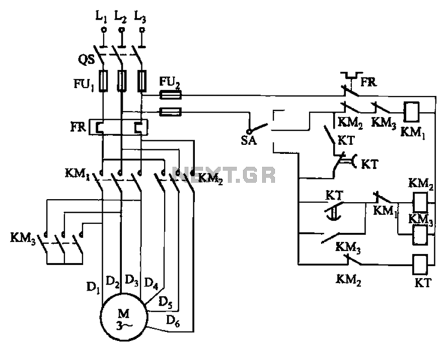
The circuit depicted in Figure 3-98 demonstrates how motor starting and low-speed operation are managed using switch SA. By adjusting the time relay KT, the motor's operation can transition from low speed to high-speed operation within a specified time...