
Gas Generator Voltage Control Circuit
The described power supply system is a sophisticated arrangement designed to optimize the electrolysis process by precisely controlling the electrical parameters applied to the plate exciters. The implementation of variable voltage sources and electronic control mechanisms allows for enhanced efficiency in gas production. The use of unipolar pulse voltage d.c. not only aids in reducing electron flow but also contributes to the stability of the electrolysis process by minimizing unwanted reactions that could occur from excessive current flow.
The inclusion of an electron inhibitor circuit plays a critical role in maintaining the integrity of the system by preventing short circuits and ensuring that the current remains within safe operational limits. The ability to fine-tune the parameters of the first and second electron inhibitors allows for adaptability in various operational scenarios, accommodating different water qualities and desired gas output rates.
Furthermore, the transformer design, with its variable inductive capabilities, is essential for achieving the desired frequency adjustments that directly influence the electrolysis efficiency. By controlling the frequency of the input AC voltage, the system can dynamically respond to changing conditions, optimizing the electrolysis process in real-time.
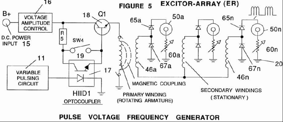
Overall, this power supply system represents a significant advancement in the field of electrolysis, specifically for hydrogen and oxygen generation from water, combining innovative circuit designs with practical applications for energy generation and storage.A power supply in a system utilizing as a source of fuel a generator for separating hydrogen and oxygen gasses from natural water and having the capabilities to control the production of gasses by varying the amplitude of the voltage and/or the pulse repetition rate of the voltage pulses applied to a pair of plate exciters in a vessel of natural w ater, comprising a sequence of circuitry operative to limit the current of a d. c. potential to a minimum value relative to the magnitude of the voltage applied to the plate exciters. The circuits each function up to a given magnitude of voltage to inhibit and curtail the flow of electrons from the plate exciter having the negative voltage potential applied thereto. The first circuit operative from a first magnitude of voltage comprises converting the voltage potential applied to the plate exciters to a unipolar pulse voltage d.
c. of a repetitive frequency. The next circuit varies the duty cycle of the unipolar pulse voltage d. c. ; followed by rearranging the application of the voltage to the exciters to individual exciters each having the voltage applied thereto independently of the other plate exciters in the generator. The next circuit comprises an electron inhibitor that prevents the flow of electrons; the circuit being in the terminal line between the negative plate exciter and ground.
In those applications of the generator wherein excessively high voltage is to be applied to the plate exciters for a very high yield of gasses, a second electron inhibitor of a unique structure is serially connected with the first electron inhibiter. The second named inhibiter having a relatively fixed value and the first inhibiter connected in series is variable to fine tune the circuits to eliminate current flow.
In a generator for producing a mixture of hydrogen and oxygen and other dissolved gas from natural water which generator includes at least a pair of plate exciters within a water containing vessel, a variable voltage source for applying a pulsating predetermined potential difference between the plates and wherein the rate of production of the mixture of gasses is controlled by varying at least one of the amplitude of the voltage and the pulse repetition rate of the pulsating potential difference applied to the plate exciters. The variable voltage source includes a means for restricting the current flow between the plate exciters to a minimum value relative to a predetermined potential difference applied to the plates, the improvement in the means for restricting said current flow comprising: variable voltage source means for converting an input voltage potential to unipolar d.
c. voltage pulses that are applied to the exciter plates and have a pulsating potential difference when measured from an arbitrary ground. There is also a means for regulating the voltage pulses in a repetitive frequency to inhibit the current flow caused by electron leakage between the plate exciters resulting from the amplitude of the applied voltage potential whereby said current flow is inhibited from exceeding a first minimum level.
The input voltage is an alternating current voltage and said circuit for converting said alternating current voltage to unipolar d. c. voltage pulses further comprises, means for varying the frequency of said alternating current voltage input to further inhibit electron leakage upon increasing the amplitude of the voltage applied to the plate exciters to a second level.
The variable voltage source is an alternating current voltage for converting alternating current voltage to unipolar d. c. voltage pulses also comprises a transformer having primary and secondary windings, and a rectifier circuit connected across said secondary windings.
The transformer further includes variable inductive means for varying the output frequency of the voltage induced in said secondary winding to further inhibit electron leakage upon in 🔗 External reference
Related Circuits
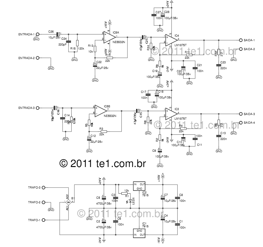
The LM1875 delivers 20 watts into a 4 or 8-ohm load on ±25V supplies. Using an 8-ohm load and ±30V supplies, over 30 watts of power may be delivered. The amplifier is designed to operate with a minimum of...
A 12V battery pack from a PowerWheels car is used alongside two wooden planks with several nails driven through them. Each nail is wrapped with speaker wire that connects to ignitors, while the other end returns to a central...
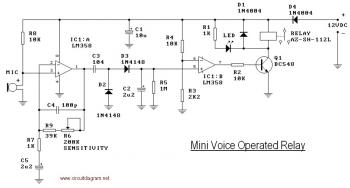
This circuit diagram illustrates a voice-operated relay, which functions similarly to a sound-activated switch circuit. It activates and deactivates the switch based on sound input. The output switch of this circuit is controlled by a relay. The release time...
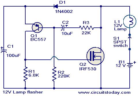
This circuit is a straightforward yet effective solution for flashing 12V lamps, particularly those utilized in automobiles. The flashing mechanism relies on transistor Q1 (BC557) and MOSFET Q2 (IRF530), with Q2 delivering the required drive for the lamp. The...
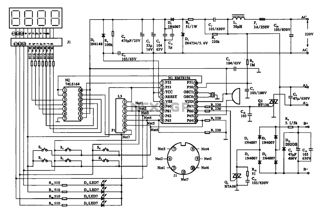
The display circuit is utilized in a typical digital massager. At the heart of the control circuit is the microprocessor EM78156, which receives manual operation instructions. It triggers two transistors to supply voltage to the DC motor (A +,...
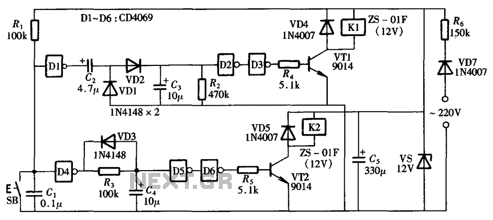
A one-button control switch is designed to control two relays, each of which can switch the load power on and off as needed. The circuit primarily consists of a hex inverter CD4049 and two self-locking DC relays. The circuit utilizes...