
Hi Fi headphone amplifier circuit diagram
The LM4880 is designed for applications requiring high fidelity audio amplification, making it suitable for portable audio devices, headphones, and other audio output systems. The dual-channel output allows for stereo sound, enhancing the listening experience. With a power output of 250 mW into an 8-ohm load, it is capable of driving standard headphones and small speakers effectively.
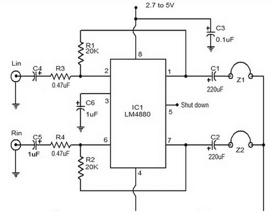
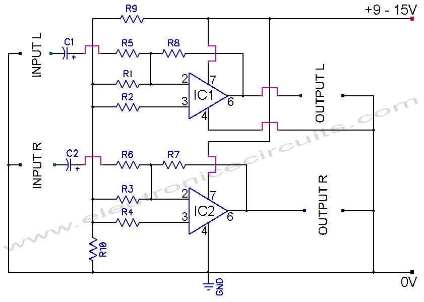
The feedback resistors R1 and R2 are critical for maintaining stability and controlling the gain of the amplifier. The choice of resistor values will determine the overall gain of the circuit, which can be calculated using the formula: Gain = 1 + (R2/R1). Careful selection of these components ensures optimal performance and minimizes distortion.
Capacitors C4 and C5 are employed to decouple the DC input, which prevents fluctuations in the power supply from affecting the amplifier's performance. This is crucial in maintaining sound quality, as any noise or ripple in the supply voltage can translate into audible artifacts in the output.
C3 serves as a filtering capacitor that helps to smooth out any remaining noise in the power supply, providing clean power to the amplifier. This is particularly important in audio applications where clarity and fidelity are paramount.
The shutdown feature, controlled by pin 5, allows for power savings when the amplifier is not in use. When a low logic signal is applied to this pin, the amplifier enters a low-power state, reducing overall power consumption. This feature is beneficial in battery-operated devices, extending their operational life.
Finally, C6's role as a half-supply filter assists in stabilizing the amplifier's operation by providing a reference voltage, which helps in maintaining consistent performance across varying load conditions. Properly implementing these components within the circuit ensures that the LM4880 achieves its intended purpose of delivering high-quality audio amplification with minimal distortion and noise.LM4880 is a dual audio HiFi amplifier IC from National Semiconductor. This headphone amplifier circuitis specifically designed to produce high quality audio output with a minimum amount of components. LM4880 integrated circuit capable of delivering 250mW per channel into 8ohm load. IC has a THD of 0.1% and has a voltage range of 2.7V to 5VDC. In th e circuit shown above, the resistors R1 and R2 are the feedback resistor. C4 and C5 are DC input decoupling capacitor. Filtering capacitor C3 provide power and reduce noise. The amplifier automatically shuts off whena low logic level is given to the shut down pin(pin5). The capacitor C6 is working at half-supply filtering. 🔗 External reference
Related Circuits
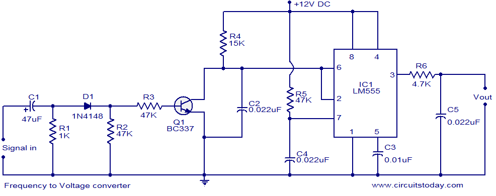
A simple frequency to voltage (F to V) converter circuit utilizing the LM555 Timer IC. This circuit has numerous applications in digital frequency meters, tachometers, and other related devices. The frequency to voltage (F to V) converter is a crucial...
555 timer circuits LM555 - Astable Oscillator Calculator, Capacitor Calculator, Basic Circuits for the LM555 Timer, Triggering and Timing Helpers for Monostable Timers, Controlling Circuits for LM555 Timers, Advanced Circuits for the LM555 Timer, LM556 Timers with Complementary or...
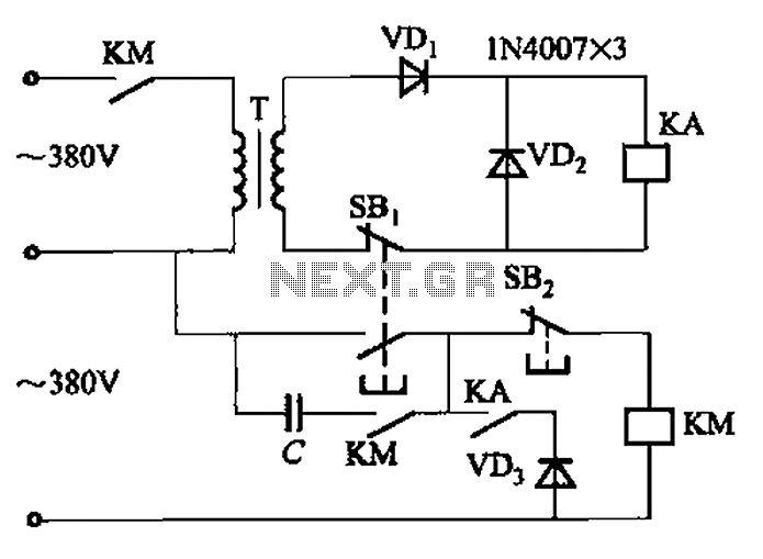
The AC contactor DC transformer circuit operates using various types of transformers and AC contactors in a DC application. The AC contactor DC transformer circuit is designed to control and manage electrical power in applications where alternating current (AC) is...
741 Stereo PreAmplifier Circuit Diagram. This preamp circuit provides better than 20dB gain in each channel. PARTS LIST R1 -.. The 741 stereo preamplifier circuit is designed to amplify audio signals with a gain of over 20 dB in each...
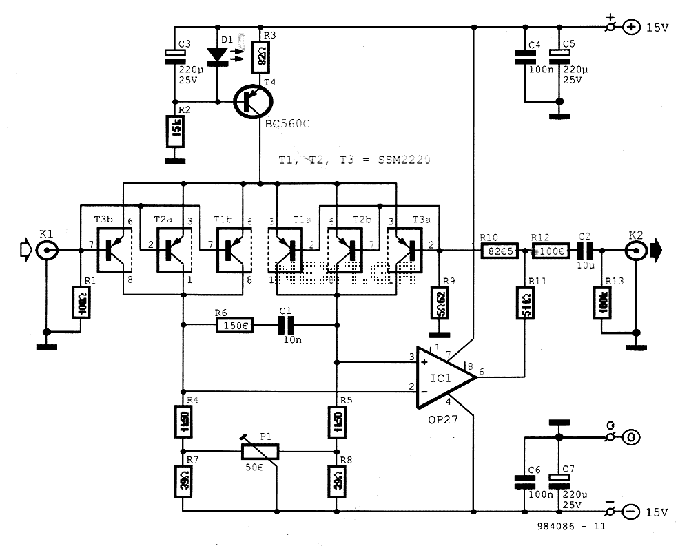
The preamplifier is designed for signal sources such as low-impedance moving coil cartridges (MC) used in high-fidelity turntables. The amplifier has an impedance of 100 ohms. To maintain low noise levels, three double-type transistors, either MAT03 or SSM2220, are...

The duty cycle of the capacitive circuit is very low, ranging from 1% to 10%. When the current is only 50 mA, the battery current consumption is just 1 A. Resistor R4 and capacitor C control the opening time,...