
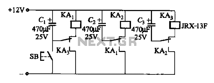
Transformer AC contactor DC operation circuit b

The AC contactor DC transformer circuit is designed to control and manage electrical power in applications where alternating current (AC) is converted to direct current (DC). This circuit typically involves the use of a transformer that steps down or steps up the voltage level of the AC supply, followed by an AC contactor that acts as a switch to control the power flow.
In this configuration, the transformer is crucial for isolating the AC supply from the DC load while ensuring that the voltage is appropriately adjusted for safe operation. The AC contactor, which is an electromechanical switch, is utilized to turn the circuit on or off based on control signals, providing a reliable means to manage high-power loads.
The design of this circuit includes several key components: the transformer, the AC contactor, rectifiers for converting AC to DC, and protection devices such as fuses or circuit breakers to prevent overloads. The rectification process is typically achieved through a diode bridge, which allows current to flow in one direction, thus converting the AC signal into a usable DC voltage.
This type of circuit is commonly used in industrial applications, automation systems, and various electronic devices where DC power is required but sourced from an AC supply. Proper selection of components and careful consideration of the circuit layout are essential to ensure efficiency, reliability, and safety in operation.AC contactor DC transformer circuit has run a variety of types, Transformer AC contactor DC operation circuit b
Related Circuits
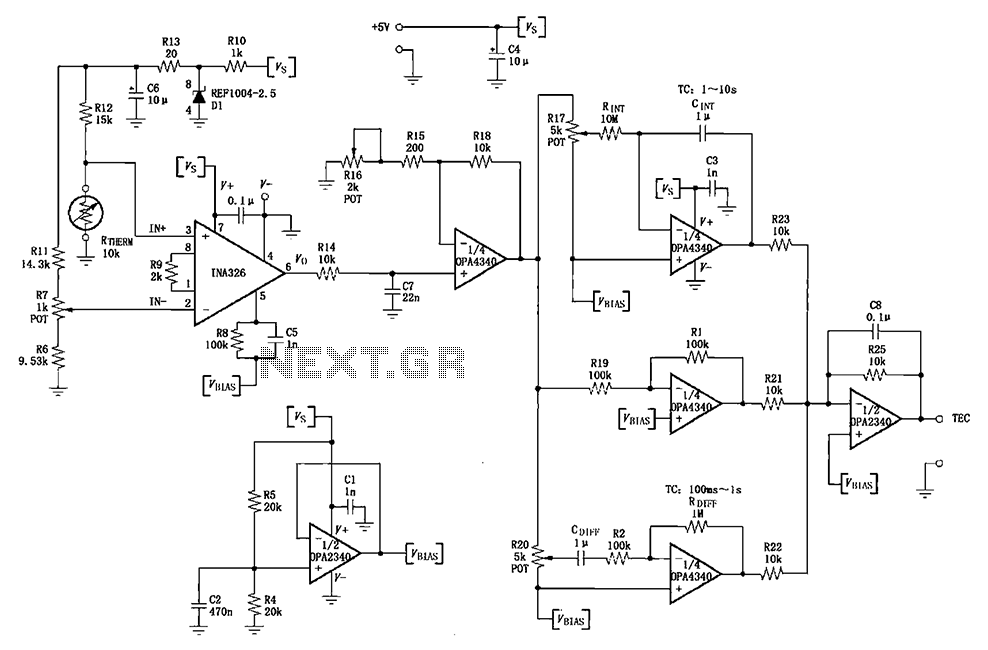
The INA326/327 forms a single power PID (proportional-integral-derivative) controller as illustrated in the temperature control loop. This circuit is primarily designed for temperature measurement and control. A thermistor, designated as RTHERM, detects temperature changes and converts them into an...
The use of diode rectifiers in AC voltmeters with a low lower limit of measurement range (0.5-1 V) leads to significant nonlinearity of the scale due to the nonlinearity of the current-voltage characteristics of diodes. The incorporation of electronic...
The automatic sprinkler controller circuit consists of a +12 V power supply circuit, a light control circuit, and an irrigation control circuit, as illustrated in the accompanying figure. The +12 V power supply circuit includes a knife switch (Q),...
A light dimmer circuit is utilized to adjust the brightness of a lamp to various levels. This dimmer circuit is designed specifically for incandescent lamps, and it is not suitable for use with fluorescent lamps. The light dimmer circuit typically...
The Johnson 275 watt and Kilowatt Matchboxes are often seen as exaggerated and unfairly criticized. They are neither exceptional tuners nor poorly designed. The main drawbacks include the fixed coupling link and the fact that they are balanced voltage...
The relay control allows for multiple pairs of contacts to be connected in parallel, enabling the circuit to handle a large lamp power. The design is straightforward; by simply changing the capacitance of the capacitor, different flash frequencies can...