
Interfacing 16x2 LCD with 8051 microcontroller. LCD module theory circuit diagram and program in assembly language
The integration of a 16x2 alphanumeric LCD module with the AT89S51 microcontroller involves several key components and steps to ensure proper operation. The JHD162 LCD module typically features a 16-character by 2-line display, making it suitable for various applications that require textual output.
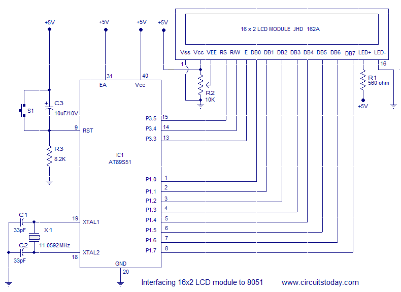
The circuit design includes a connection between the microcontroller and the LCD module, where the microcontroller sends commands and data to control the display. The JHD162 LCD has a specific pinout that includes power supply pins (VSS, VDD), a contrast adjustment pin (V0), and data pins (D0-D7) for 8-bit communication, along with control pins such as RS (Register Select), RW (Read/Write), and E (Enable).
The microcontroller AT89S51, which is an 8-bit microcontroller from the 8051 family, is programmed to interface with the LCD. The program typically initializes the LCD, sets the mode of operation, and sends characters to be displayed. The initialization sequence involves configuring the data pins and control signals, ensuring the LCD is set to 8-bit mode, and setting the cursor position for displaying text.
The schematic diagram illustrates the connections between the AT89S51 and the JHD162 LCD module. It shows how the microcontroller's output pins are connected to the LCD's data and control pins, along with the necessary power supply connections.
In summary, the interfacing of a 16x2 alphanumeric LCD module with the AT89S51 microcontroller encompasses a well-defined circuit design, an understanding of the LCD's pinout and command set, and a programmed microcontroller to manage the display of textual information effectively.Interfacing 16x2 alphanumeric LCD module with AT89S51 microcontroler. Circuit diagram,theory and program. JHD162 lcd module pinout and commands.. 🔗 External reference
Related Circuits

The relay power in the linear circuit is derived from a -120 V bias supply, while the transmit keying output from the Kenwood device is +12 V with a maximum current of 10 mA. A critical component of this...
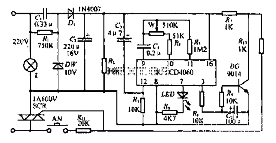
The circuit includes a CD4 component with a connection of 16 feet for the Vcc terminal, 8 feet for the ground, 12 feet for the reset terminal, 7 feet for the Qt end, and 3 feet for the Q...
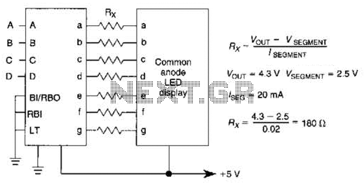
An IC1, such as the 7447, drives a common anode 7-segment LED display. The current-limiting resistor R must restrict the segment current to the rated value at the maximum supply voltage. A sample calculation is provided. The 7447 integrated circuit...
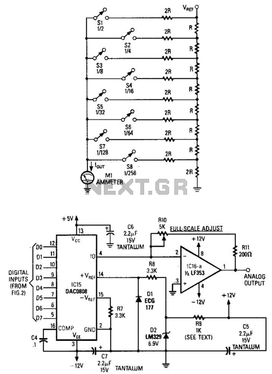
Figure A illustrates an R/2R resistor ladder. Each closed switch increases the current flow. A basic channel A/D converter is depicted in Figure B. The voltage reference (D2) is shared across all channels, although the value of the dropping...
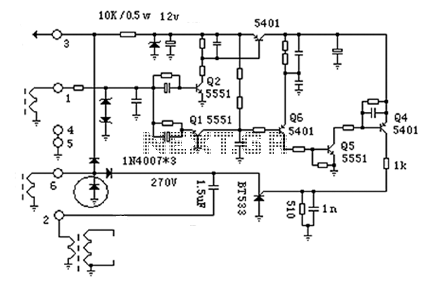
The anatomy of two ignition experiments revealed a common issue, specifically that both ends of the ignition coil are equipped with a diode. This design choice by manufacturers has implications for performance. The ignition coil generates a negative half-cycle...
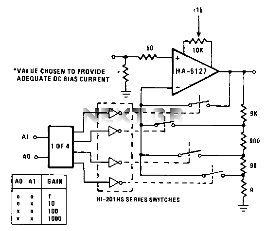
A circuit may often be required to perform multiple functions. In these cases, the variable gain configuration of the circuit can be particularly advantageous. This programmable gain stage utilizes CMOS analog switches to modify the feedback amount, thereby adjusting...