
Key code lock switch circuit
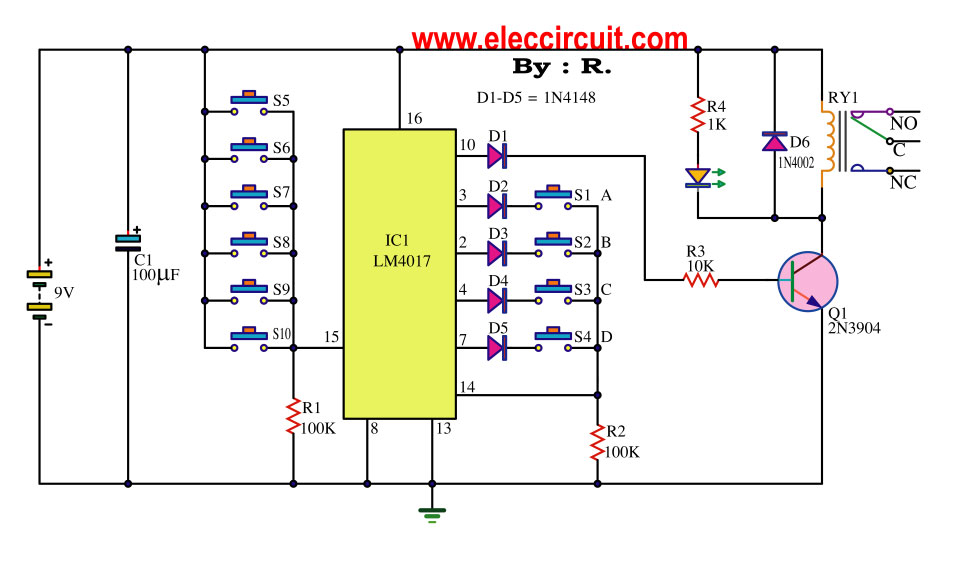
The key code switch circuit utilizes a microcontroller or a dedicated integrated circuit (IC) to interpret key codes entered by the user. This method enhances security and convenience, as it allows for various functionalities without the physical wear and tear associated with traditional mechanical switches.
Typically, the circuit comprises a keypad interface, which may consist of a matrix of buttons or a touch-sensitive surface. When a user inputs a code, the circuit processes the input through a digital signal processor or microcontroller, which compares the entered code against a pre-stored code in its memory. If the entered code matches the stored code, the circuit triggers an output signal that can activate or deactivate a connected device, such as a lock, alarm, or any electronic system requiring authentication.
Power supply requirements for this circuit are generally low, often allowing it to operate on standard batteries or a low-voltage power source. Additionally, the circuit may include features such as LED indicators to provide visual feedback on the status of the key code entry, ensuring the user is aware of successful or failed attempts.
In terms of security, the implementation of a key code switch circuit can incorporate features like timeout periods after multiple failed attempts, making it more difficult for unauthorized users to gain access. Furthermore, some designs may allow for the code to be changed periodically, adding an additional layer of security.
Overall, the key code switch circuit represents a modern solution for secure access control, combining user-friendly design with advanced electronic functionality.This key code switch circuit is a type of electronic circuit that is created to replace conventional normal key switch. Without inserts a keys. But you can.. 🔗 External reference
Related Circuits
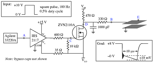
A copper mesh measuring 10 cm x 10 cm is situated in a vacuum chamber and connected to a BNC connector via a 24 cm copper wire. The objective is to rapidly switch the voltage across the mesh (referenced...
The amplifier circuit utilizes negative current feedback, which ensures that the load current is primarily influenced by the input signal rather than the loudspeaker's impedance. The inductor current from the loudspeaker generates a voltage across resistor R7, which is...
This is a design for a flashlight that two 220 V alternating lights can control. The flashlight uses only one IC. IC1a IC1c to be used for the flashing signal generation. The output of IC1c thyristor T1 is controlled,...
This webpage outlines the radio transmitter unit that was part of the Cirrus One rocket mission in April 2001. The transmitter was included as a payload due to concerns about recovery challenges if the rocket drifted far downrange after...

Typically, home appliances are controlled using switches, sensors, and similar devices. However, physical contact with switches can pose risks, especially in the event of a short circuit. The circuit outlined here eliminates the need for physical contact to operate...
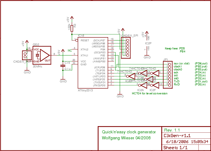
The design generates varying sampling clock write strobe pulses using an ATtiny2313 microcontroller from Atmel. For a 10MHz sampling clock, a 20MHz clock is required for the ATtiny2313, necessitating a power supply of 5V instead of 3.3V, which is...