
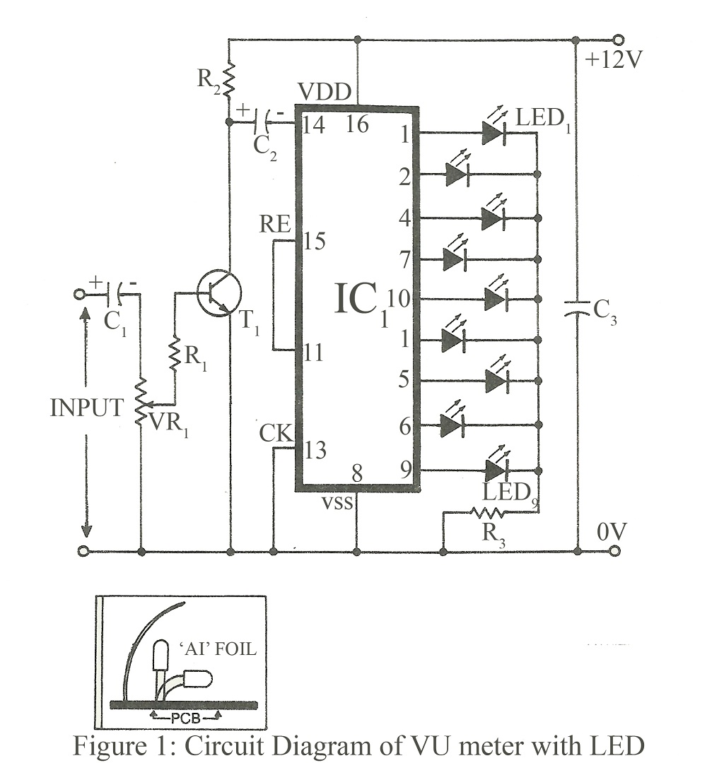
Led Running Lights

The circuit design can be divided into three distinct functional blocks: the oscillator, the mod 16 counter, and the LED driver section.
The oscillator is designed to operate in a self-triggered mode, which ensures continuous operation without the need for an external clock signal. The frequency of oscillation can be adjusted using the variable resistor (VR1), allowing for a broad range of frequencies. This feature is particularly useful for applications requiring dynamic light effects, as it enables the user to fine-tune the speed of the running lights.
The mod 16 counter (7493) serves as the core counting mechanism, producing binary outputs corresponding to its count value. The outputs A, B, and C are directly connected to the decoder IC3 (7442), which converts the binary count into a decimal output. The decoder outputs are available on pins 1 to 9, which can drive multiple LEDs, providing visual feedback of the counter's state.
The D output of the counter plays a crucial role in determining which set of LEDs is illuminated. The circuit is designed such that when the D output is low, it activates the first set of LEDs (D1 to D8). Conversely, when the D output is high, the second set of LEDs (D9 to D16) is activated. This dual selection mechanism allows for a more extensive range of visual effects.
The NAND gate (IC4, 7400) is utilized to facilitate the selection process of the LEDs. This gate effectively manages the logic required to switch between the two groups of LEDs based on the state of the D output from the counter. The result is a visually appealing sequential running light effect, where the LEDs light up in a predetermined sequence, creating an engaging display.
Overall, this circuit exemplifies a practical application of digital electronics, combining oscillation, counting, and LED driving techniques to achieve a dynamic and adjustable lighting effect.The circuit consists of three parts. The first part has an oscillator while the second has mod 16 counter 7493. The oscillator is wired in self-triggered mode, and the potentiometer VR1 is used for speed control of the running lights. That is, frequency can be varied from 21 Hz to less than 1 Hz. The counter outputs A, B and C are decoded by IC3 (t he decoder 7442) and the outputs obtained on pins 1 to 9 of this IC. The D output of the counter is used for selecting the LEDs from D1 to D8 or D9 to D16. When D is low D1 to D8 are selected, and when D is high D9 to D16 are selected. For the selection of these LEDs, IC4 (7400) NAND gate is used. Thus, a sequential running effect is produced. 🔗 External reference
Related Circuits
The finger, positioned within a light screen, is situated between a high-intensity LED emitter and a photocell. It generates a heartbeat signal that, when appropriately amplified, serves as the input for a PIC16F84 microcontroller. The microcontroller drives three common...
A LED is used to indicate when a DC voltage reaches 5 volts or more. The LED should be fully illuminated at 5 volts and not dim at 4.5 volts or lower. The circuit should be constructed using discrete...
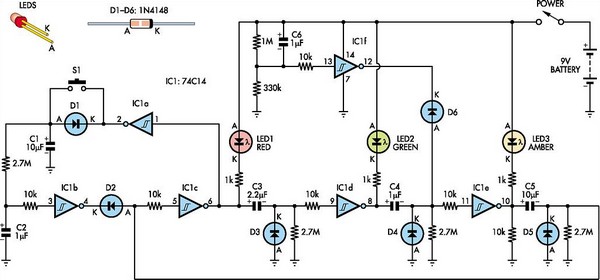
This toy traffic signal utilizes a single, cost-effective hex Schmitt-trigger inverter IC (IC1a-IC1f) to directly control three colored LEDs (red, green, and amber). Upon activation, the circuit illuminates the red signal for 30 seconds, followed by the green signal...
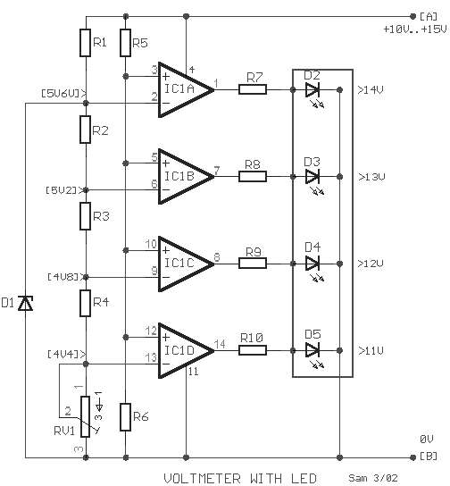
The circuit is a comparator that measures the voltage of a car battery in steps of 1 Volt. The voltage measurement is performed by comparing the battery voltage, applied to the inverting inputs of amplifiers, against reference voltages produced...
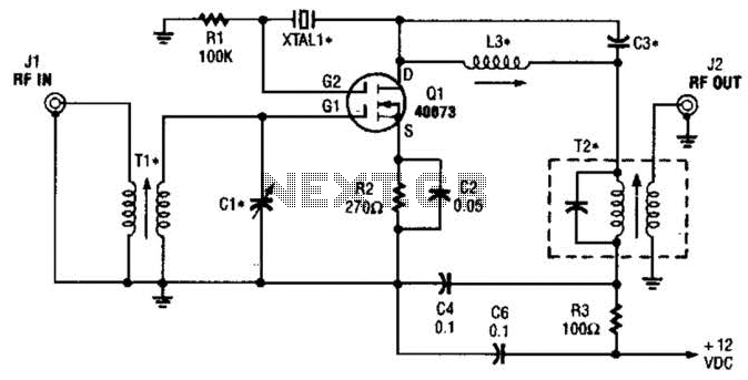
The second gate (G2) of a MOSFET can be utilized to integrate a crystal oscillator within the same stage as a frequency mixer. While this technique is common in tube technology, it is rarely implemented in dual-gate MOSFET circuits....
When constructing a stereo amplifier or if one is already owned, it is beneficial to incorporate this circuit. The entire setup is based on the IC4017, with its clock input connected through a BC107 transistor. The IC4017 functions as...