
Motor electronic speed controller circuit diagram 7

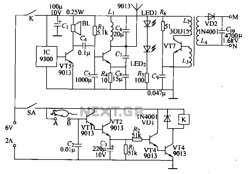
The electronic motor speed controller circuit is designed to facilitate the remote control of motor speed, enhancing operational flexibility in various applications. The transmitter section utilizes a micro-power wireless remote control transmitter IC module (IC1) that generates control signals. This module is typically designed to operate at low power, ensuring longevity and efficiency in battery-operated devices.
The time-base integrated circuit (IC2) plays a critical role in generating precise timing signals, which are essential for modulating the output frequency sent to the motor. This modulation is vital for achieving varying speed levels in the motor operation. The inclusion of diodes VD1 and VD2 serves to protect the circuit from reverse polarity and voltage spikes, ensuring the integrity and longevity of the components.
The receiver circuit, which is not detailed in the initial description but is implied, would typically include a corresponding wireless receiver module that decodes the signals transmitted by the transmitter. This module would then relay the control signals to a motor driver circuit, which translates the signals into appropriate voltage and current levels to control the motor speed effectively.
Overall, the integration of these components enables a reliable and efficient wireless control system for motor speed regulation, suitable for applications ranging from remote-controlled vehicles to automated industrial processes.The electronic motor speed controller circuit consists of wireless remote control transmitter circuit, wireless remote control receiver control circuit, and it is shown as the chart. Wireless remote control transmitter circuit is composed of the micro-power wireless remote control transmitter IC module IC1, time-base integrated circuit IC2, diodes vD1, VD2,..
🔗 External reference
Related Circuits
The circuit is a bell timer. This project utilizes the AT89S52 microcontroller and an I2C EEPROM for storing alarm timings. Additionally, the 7-segment display has been replaced with an LCD display. The DS1307 is employed for real-time clock functionality....
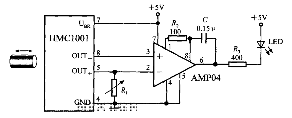
The circuit depicted in the figure includes the HMC1001 magnetic sensor, an operational amplifier (AMP04), and a light-emitting diode (LED), forming a proximity switch circuit. In this application, the operational amplifier functions as a comparator. When a magnet, approximately...
Power-saving electronic mousetrap. This example describes the minimal power consumption, which only occurs when a mouse enters the control zone during foraging activities. After a 30-second delay, the system enters a wait state, making it suitable for outdoor use....
When an individual touches the safety box or other protected metal objects, the sensor circuit generates a pulse to the alarm circuit. The positive edge of this pulse activates the semiconductor and thyristor flash GE, subsequently triggering the camera...
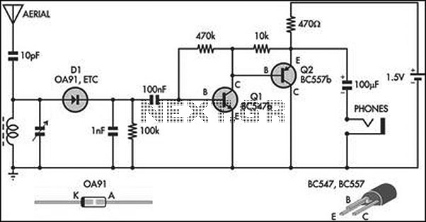
This circuit is an amplified crystal set. The inductor can be a standard AM radio ferrite rod antenna, while the tuning capacitor is a variable plastic dielectric gang designed for small AM radios. The aerial tuned circuit feeds diode...
Some relays will become warm if they remain energized for some time. The circuit shown here will actuate the relay as before but then reduce the hold current through the relay coil by about 50%, thus considerably reducing the...