
RF detector electronic project circuit design using 2N2222 transistors

This RF detector circuit is a versatile tool for various applications, including amateur radio, signal analysis, and educational projects. The design incorporates a straightforward configuration that allows for easy assembly and troubleshooting. The use of common transistors such as the 2N3906 and PN2222A ensures that the circuit can be built with readily available components.
The circuit operates by first capturing RF signals through an antenna, which feeds into the detector diode. The diode rectifies the RF signal, converting it into a DC voltage that can be processed by the following stages. The biasing of diode D2, adjusted using potentiometer R2, is critical for optimizing the sensitivity of the detector. This adjustment allows the circuit to effectively respond to a wide range of signal strengths, ensuring reliable operation under varying conditions.
For enhanced performance, particularly in low-signal environments, the addition of a wideband RF amplifier between the antenna and the detector diode is recommended. This amplifier boosts the incoming RF signals, improving the overall sensitivity of the detector. Careful layout considerations, such as keeping the leads of the diode and capacitor (C1) short, help reduce stray inductance, which can adversely affect performance.
The visual indication of signal reception can be implemented using an LED, while an audible indication can be achieved with a small speaker or piezo buzzer. This dual-indication system allows the user to easily identify the presence of RF signals, making the circuit practical for field use.
In summary, this RF detector circuit is a compact and effective solution for detecting a wide range of RF signals, with straightforward adjustments for sensitivity and easy integration of additional components for enhanced performance.This electronic rf detector electronic project is designed using common transistors and other few common electronic parts. This rf detector responds to RF signals bellow the standard broadcast band to well over 500 MHz and provides an visual, and audible indication when the signal is received.
By adjusting the bias of D2 with the R2 potentiomete r the circuit can detect low power or strong signals. The circuit can be powered using a simple 9 volts battery or any other 9 volts DC power supply circuit. If the rf detector is not enough sensitive you can connect a good wideband RF amp between the antenna and the detector diode.
Keep diode and capacitor (C1) leads short to minimize stray inductance. The used transistors can be : 2N3906, 2N2907 or other PNP high gain transistor for Q2 and PN2222A, 2N3904 or other NPN high gain transistor for Q1. 🔗 External reference
Related Circuits

This add-on circuit can be attached to the solar charger to indicate whether the battery is charging. It lights a red LED to signal that the battery is charging. The described add-on circuit serves as a visual indicator for the...
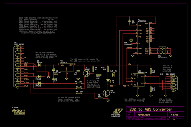
The new version of the RS485 interface addresses the issues associated with RTS control, which was a challenge in the previous design. However, implementing this solution requires a microprocessor, adding complexity to the design. This unit is currently being...
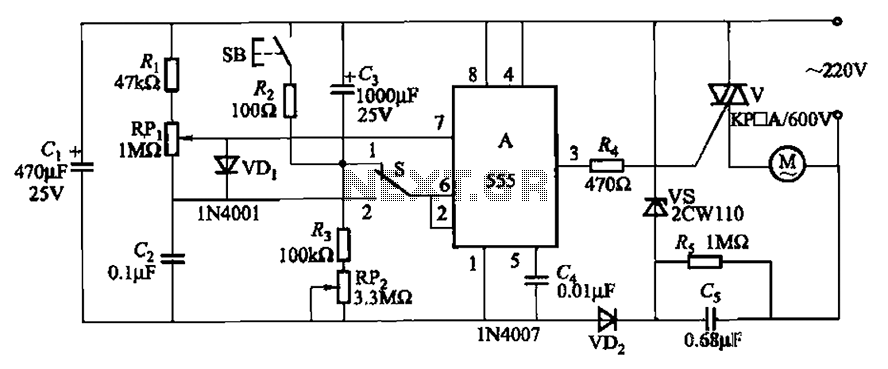
The circuit illustrated in Figure 3-12 incorporates variable speed and timing control functions. When switch S is set to position 1 and button SB is pressed, the motor initiates operation. After a predetermined delay, the motor automatically shuts down....

This white LED driver circuit operates up to four white LEDs in parallel from a 3.3V power source, adjusting the total LED current from 1mA to 106mA in 64 steps of 1dB each. The brightness control of the LEDs...
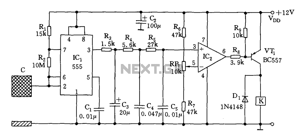
The switch circuit consists of a capacitive oscillator, an integration network, and a comparator circuit that controls a relay. When a body comes close to the induction plate, the inductive capacitance to ground increases, causing the 555 astable multivibrator...
This document details the AT Keyboard Interface and AT Keyboard Protocols. It includes an example of a Keyboard to ASCII decoder utilizing a 68HC705J1A microcontroller. The AT Keyboard Interface is a standard communication protocol used primarily in personal computers to...