
Schematic Diagram TA8122 AM-FM radio receiver circuit

The TA8122 integrated circuit is designed to facilitate the construction of low-power radio receivers. It integrates essential functions required for AM and FM reception, including demodulation and audio amplification. The device operates efficiently within a voltage range of 1.7V to 7V, making it versatile for various battery-operated applications. For optimal functionality, a 3V power supply is recommended, which can be easily achieved using two standard 1.5V batteries in series.
The circuit typically includes a few passive components such as resistors and capacitors, which are crucial for tuning and filtering signals. An antenna is also required to capture radio waves effectively. The design may incorporate additional components like variable capacitors or inductors to enhance selectivity and sensitivity, depending on whether the receiver is intended for AM, FM, or both bands.
In constructing the circuit, it is important to ensure proper layout and grounding to minimize noise and interference, which can significantly impact radio performance. The output can be connected to a small speaker or headphones, allowing for audio playback. The simplicity of the TA8122 circuit design makes it an excellent choice for hobbyists and educational purposes, providing a practical introduction to radio frequency electronics.A very simple low power AM FM radio receiver electronic projects can be designed using the TA8122 integrated AM FM receiver, manufactured by Toshiba Semiconductor. This radio receiver circuit can be used for portable radio applications or other similar devices. TA8122 radio receiver circuit supports a wide input voltage range from 1. 7 volt up t o 7 volts, but for this AM FM radio receiver circuit we will need just a 3 volt DC input voltage ( you can use two 1. 5 volt Batteries ). Using this receiver integrated circuit you can design a very simple AM FM radio receiver or a radio receiver circuit that supports just one of this band (AM or FM) using few additional components.
🔗 External reference
Related Circuits

PCM Powercom was established in 1987 and is a prominent provider of power protection products, holding an ISO 9001 certification. The company employs more than 2,600 individuals globally. PCM Powercom specializes in the design and manufacture of power protection solutions,...
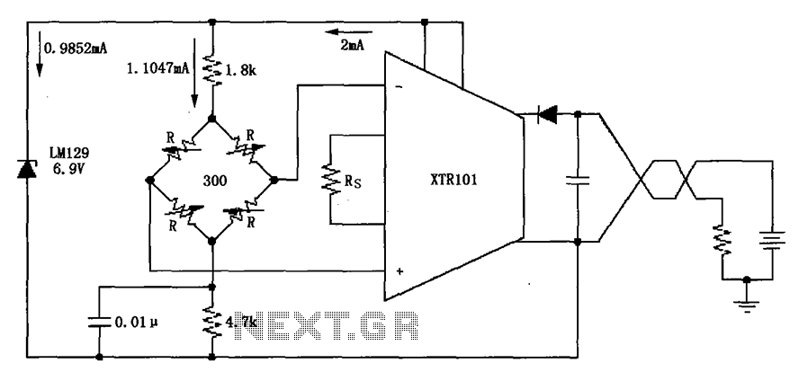
The circuit utilizes the LM129 voltage regulator to produce a 6.9V voltage reference, supplying a current of 1.0147mA from the 6.9V reference voltage to the bridge. The bridge may consist of varistor-type pressure sensors. The LM129 voltage regulator is a...
The connection and wiring between each part and component of the exterior lighting system of the vehicle includes elements such as the fusible link, junction block, tail light relay, cruise control, stop light switch, relay box, column switch, rear...
Electronics tutorial on mesh current analysis and examples of mesh analysis used to analyze complex electrical circuits in DC theory. Mesh current analysis is a powerful technique used in circuit analysis to determine the currents flowing in the loops of...
This intelligent electronic lock circuit is constructed using only transistors. To unlock this electronic lock, the user must press tactile switches S1 through S4 in sequence. For added security, these switches can be labeled with different numbers on the...
Video-DVM is a very cheap DVM that shows how an output as complex as a videocomposite signal can be generated entirely in software: two I/O pins and three resistors are all the hardware required. Connected to any TV set...