
Simple Alarm Circuit
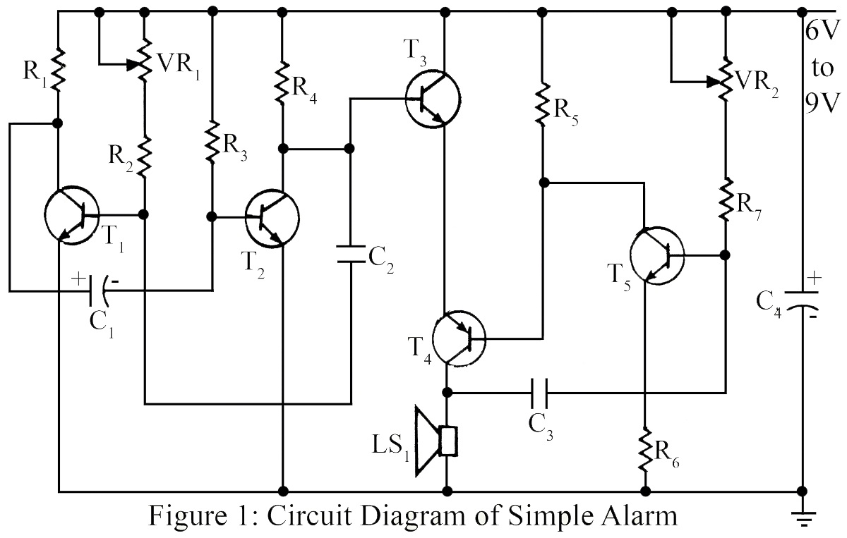
This circuit operates as a basic burglar alarm system designed to emit an audible sound when triggered. The core component of the circuit is a transistor-based oscillator, which generates a square wave signal. The five transistors are configured in a manner that allows for both signal amplification and control of the alarm's sound output.
The first stage of the circuit typically involves a pair of transistors configured as a multivibrator. This arrangement produces a continuous oscillation that creates a square wave. The frequency of the oscillation can be adjusted by varying the resistor and capacitor values in the circuit, thus allowing for customization of the alarm tone.
The output from the multivibrator is fed into additional transistors that serve as amplifiers. These transistors increase the current driving capability of the circuit, allowing it to activate a speaker or piezo buzzer effectively. The speaker, when powered by the amplified signal, produces the audible alarm sound that alerts individuals to the potential security breach.
To enhance functionality, the circuit may include a triggering mechanism, such as a motion sensor or a magnetic switch, which activates the alarm when unauthorized entry is detected. This triggering mechanism can be connected to the base of one of the transistors, ensuring that the oscillator circuit is powered only when the alarm is in a triggered state.
Overall, this simple transistor-based burglar alarm circuit is effective for basic security applications, providing an audible notification to deter intruders. Its straightforward design allows for easy assembly and modification, making it suitable for educational purposes or as a foundation for more complex alarm systems.The simple circuit produces simple audible alarm like notification of sound, used as burglar alarm using five transistor. 🔗 External reference
Related Circuits
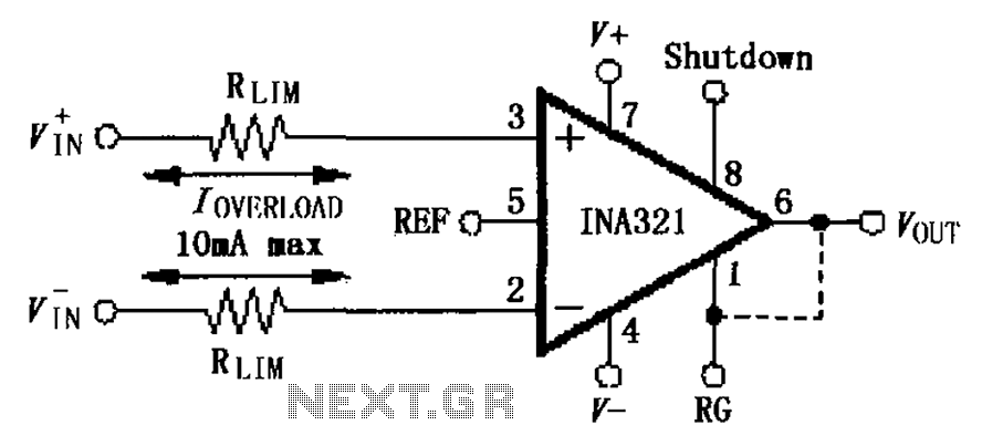
The input current protection circuit for the INA321/322 is illustrated. The INA321/322 features input terminal electrostatic discharge (ESD) protection diodes that become conductive when the input voltage exceeds the supply voltage by 500mV. The protection diodes will conduct, and...

How to create a hydrogen generator using a 555 timer circuit with Pulse Width Modulation (PWM). This PWM circuit can generate hydrogen on demand. The hydrogen generator circuit utilizing a 555 timer operates by controlling the duty cycle of the...

This remarkably straightforward circuit enables the operation of one or two robust 12V 21W car bulbs in a flashing mode using a power MOSFET. Such devices are especially suitable for road, traffic, and yard alerts, as well as in...

The circuit illustrated in Figure 3-145 employs a rectifier diode brake for neutral grounding in a three-phase, four-wire power supply system. This circuit design incorporates a rectifier diode brake, which plays a crucial role in ensuring the safety and reliability of...

How many speakers can be attached to this amplifier, and what are the impedance and wattage values of these speakers? Please respond to my email. Sir, you made this amplifier, and it works properly for a lifetime. Which transformer...

Simple triangle-wave generators have a limitation in that the waveform of their output signal typically cannot be modified. The circuit presented here makes... The described circuit addresses the inherent limitation of conventional triangle-wave generators by incorporating adjustable components that allow...