
Simple FM Modulator Design
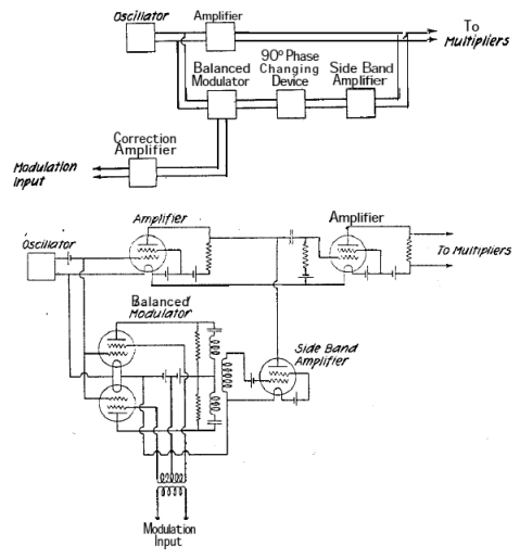
The design of an FM transmission system involves several key components, including oscillators, modulators, amplifiers, and antennas. The oscillators, which have already been constructed, are crucial as they generate the carrier signals at specific frequencies within the FM band, typically ranging from 88 MHz to 108 MHz.
To achieve multi-frequency transmission, a frequency synthesizer may be employed, allowing for precise tuning and stability across the desired frequency range. This can be accomplished using phase-locked loops (PLLs) or direct digital synthesis (DDS) techniques, which provide flexibility in frequency selection and modulation.
The modulation stage is essential for encoding the audio or data signal onto the carrier wave. This is typically achieved using a voltage-controlled oscillator (VCO) that varies its frequency based on the amplitude of the input audio signal, effectively creating frequency modulation. The modulated signal is then amplified using RF amplifiers to ensure adequate power for transmission.
The final stage involves the antenna, which must be designed to efficiently radiate the modulated signal into the surrounding environment. The choice of antenna type (e.g., dipole, monopole, or loop) will depend on the desired range and coverage area of the transmission.
Careful consideration must also be given to compliance with regulatory standards governing FM transmissions to avoid interference with other services and ensure proper licensing. Power levels, frequency stability, and bandwidth must all adhere to the relevant guidelines to maintain operational integrity and legality.
Overall, the successful implementation of an FM transmission system requires meticulous design and integration of these components to achieve reliable and high-quality signal transmission.Hello, I want to build a system that can transmit in the FM band. I have already built my oscillators because I want to transmit at more than one.. 🔗 External reference
Related Circuits
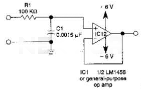
This simple filter utilizes an RC section as the filter element, incorporating a voltage follower to manage other frequencies. The -3 dB point is calculated as 1/(6.28 * RXCV), resulting in a response that drops 6 dB per octave...

This simple door chime protects the door and emits a loud alarm tone in the event of a theft attempt. The circuit is straightforward and battery-operated. A Normally Closed (NC) reed switch and magnet are utilized to trigger the...
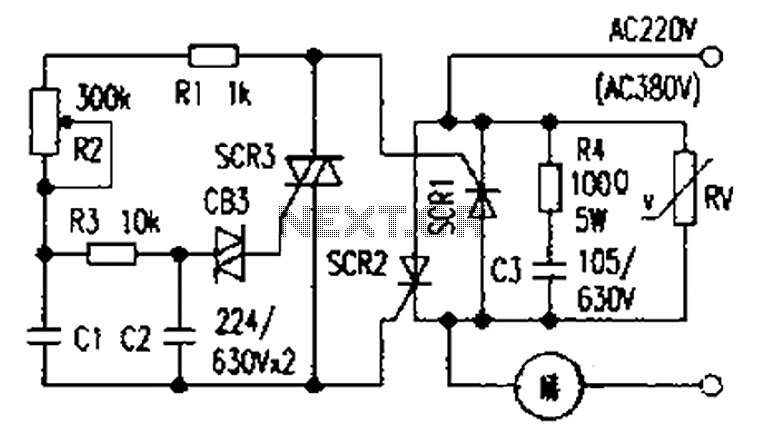
The presentation of a general power thyristor trigger circuit is more complex, and some components are difficult to procure. A successful trigger circuit has been constructed for only a few dollars. This circuit is designed to trigger a thyristor...

This circuit utilizes the widely available and user-friendly LM3914 integrated circuit (IC). The LM3914 is straightforward to operate, does not require external voltage regulators due to its built-in voltage regulation, and can be powered by nearly any voltage source....
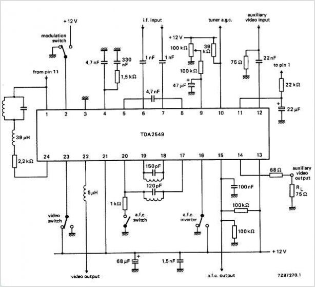
The circuits utilize two FM Demodulator TDA2555 systems to execute the demodulation functions necessary in a dual sound carrier television system for demodulating the sound carriers. The distinction between the TDA2555 and TDA2557 lies in the number of stages...
Flyback LED drivers are versatile as they can be utilized in applications with input voltages either above or below the necessary output voltages. They feature a straightforward circuit configuration that maintains a constant LED current without the need for...