
Simple Fire alarm circuit using LDR
The fire alarm circuit operates on the principle of light interruption caused by smoke, which is detected through the LDR. The LDR's resistance changes significantly in the presence of smoke, leading to a voltage change that controls the transistor's state. This transition is crucial for activating the alarm system. The tone generator IC UM66, when powered, produces a sound that serves as an alarm, while the TDA2002 amplifies this sound to a level suitable for driving a speaker, making the alarm audible.
The power supply section is designed to ensure that the circuit functions reliably under various conditions. The transformer steps down the mains voltage to a safer level, and the bridge rectifier converts AC to DC, which is then smoothed by capacitors to provide a stable voltage to the circuit. The 7809 voltage regulator ensures that fluctuations in the supply voltage do not affect the operation of the fire sensing circuit, which is critical for reliable performance.
In the modified version of the circuit, the addition of a relay allows for the control of high-power devices, such as sirens or lights, enhancing the alarm's effectiveness. The use of transistors Q1, Q2, and Q3 in this configuration allows the circuit to manage higher loads safely. The protective components, such as the freewheeling diode, ensure that the circuit remains safe and functional, even when switching inductive loads, which can generate voltage spikes.
Overall, this fire alarm circuit is an efficient and effective design for detecting smoke and activating an alarm, with the flexibility to control additional high-power devices through the relay system.Here is a simple fire alarm circuit based on a Light Dependent Resistor (LDR) and lamp pair for sensing the fire. The alarm works by sensing the smoke produced during fire. The circuit produces an audible alarm when the fire breaks out with smoke. When there is no smoke the light from the bulb will be directly falling on the LDR. The LDR resistanc e will be low and so the voltage across it (below 0. 6V). The transistor will be OFF and nothing happens. When there is sufficient smoke to mask the light from falling on LDR, the LDR resistance increases and so do the voltage across it. Now the transistor will switch to ON. This gives power to the IC1 and it outputs 5V. This powers the tone generator IC UM66 (IC2) to play a music. This music will be amplified by IC3 (TDA 2002) to drive the speaker. Resistor R6 is meant for protecting the transistor when R4 is turned towards low resistance values. Resistor R2 and R1 forms a feedback network for the TDA2002 and C1 couples the feed back signal from the junction of R1 & R2 to the inverting input of the same IC.
CircuitsToday has a list of 4 books for electronics enthusiasts who are looking for a better chance to learn the basics and getter a better practical insight of the subject. These books are written by authentic authors like Forrest M Mims, Charles Platt and so on. You can read their reviews and buy them online here:- 4 GREAT BOOKS TO LEARN BASIC ELECTRONICS. A well regulated power supply is essential for this circuit because even slight variations in the supply voltage could alter the biasing of the transistor used in the fire sensing section and this could seriously affect the circuit`s performance.
A regulated 9V/500mA power supply that can be used for powering the basic fire alarm circuit and its modified versions is shown above. Transformer T1 is a 230V primary, 12V secondary, 500mA step down transformer. D1 is a 1A bridge which performs the job of rectification. Capacitor C1 filters the rectifier output and C2 is the AC by-pass capacitor. IC1 (7809) is a 9V fixed positive voltage regulator. The output of the rectifier+filter section is connected to the input of 7805 and a regulated steady 9V is obtained at its output.
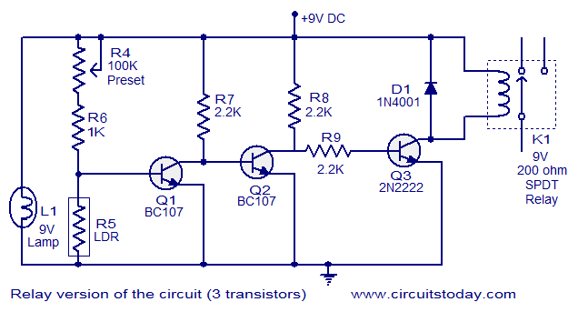
S1 is the ON/OFF switch. F1 is a 500mA safety fuse. Here the above fire alarm circuit is modified to operate a relay when the fire breaks out. The usage of relay makes the circuit able to switch high power warning devices like alarms, bells, beacon lights etc that operates from the mains. Two additional transistors are used with the basic fire sensing circuitry (consisting of Q1, R4, R5 and L1) to attain the target.
Whenever the fire breaks out the transistor Q1 is switched ON. The collector voltage of Q1 drops to 0. 2V and the transistor Q2 gets switched OFF. This makes the collector voltage of Q2 rise towards 9V and this result in the switching ON of transistor Q3. The relay connected at the collector of Q3 is activated and the load connected through the relay contact is driven.
Resistors R7 and R8 limits the collector current of Q1 and Q2 respectively. D1 is a freewheeling diode which protects Q3 from the voltage spikes induced when the relay is switched. Resistor R9 controls the base current of transistor Q3 (2N2222). 🔗 External reference
Related Circuits
This circuit can manage nine independent telephones using a single telephone line pair located at nine different locations. It functions as a bidirectional telephone line simulator without the need for actual telephone lines, allowing for coupling, testing, and demonstration...
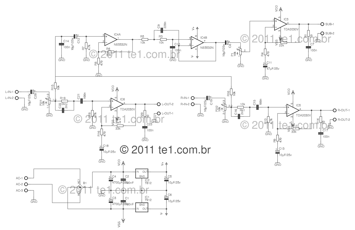
This circuit is a complete application for a 2.1 amplifier system, consisting of two satellite speakers powered by a TDA2030 and one subwoofer. This 2.1 system is commonly utilized in commercial applications as an amplifier for computers, enhancing audio...

Competition among relay contacts in contactor control systems often leads to significant issues that can be cumbersome to address. In some cases, this requires the addition of numerous components. However, utilizing a negative temperature coefficient thermistor (NTC) for delay...

The Clock Controller was designed to be an exemplary of using 'C' language to control timer0 interrupt, 7-segment LED and keypad scanning. It provides 1-bit sink current driving output, for driving a relay, opto-triac, say. Many projects requiring 7-segment...
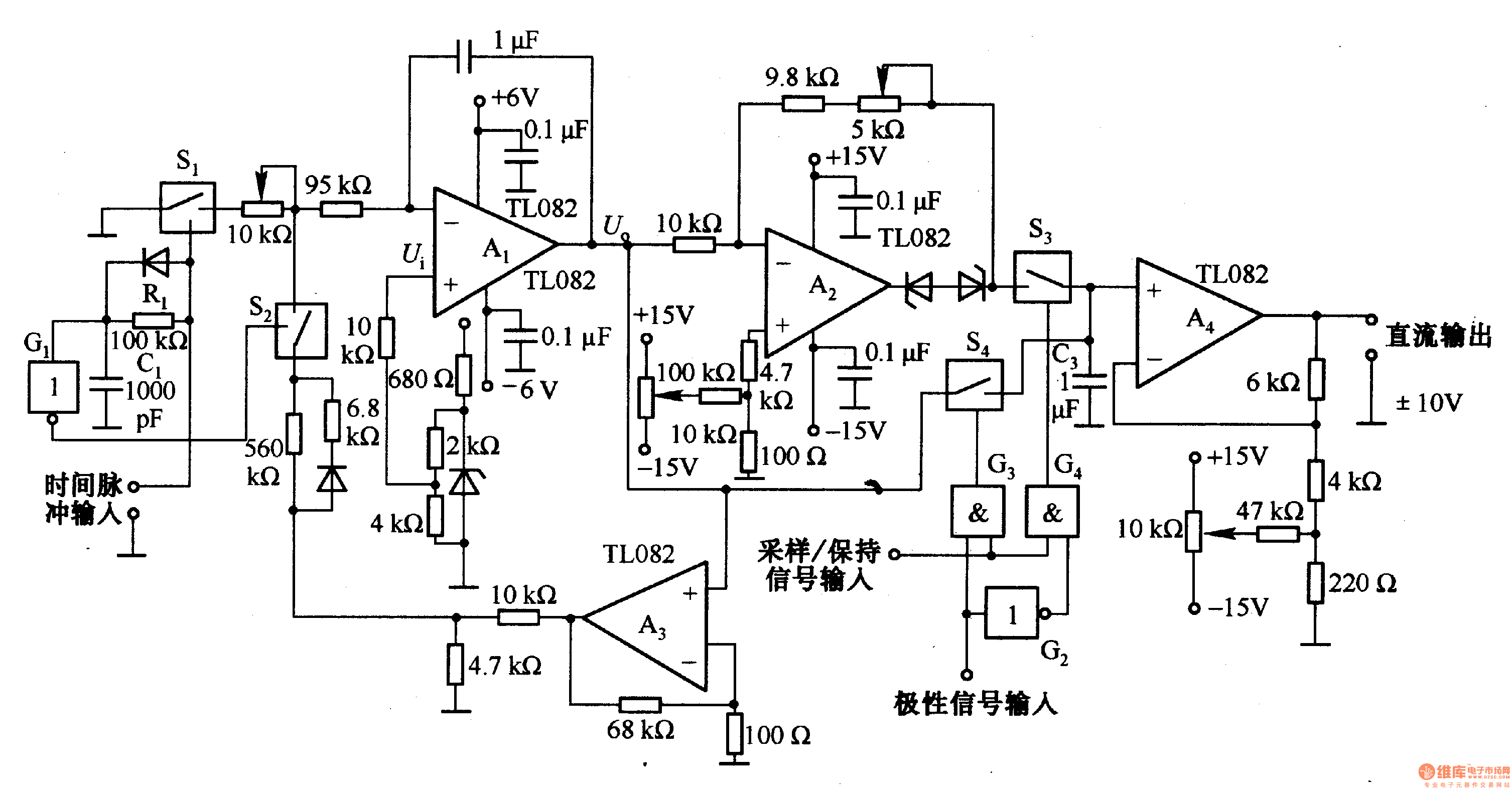
This circuit is designed for pulse width (time) to voltage conversion. According to the component parameters in the diagram, it can convert a pulse width of 0.1 seconds into an output voltage of 10V. When a conversion pulse is...
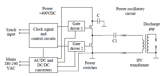
Simulate the electric field within a gas-filled discharge gap generated by a radio frequency voltage generator. The circuit, provided by the experimenters at a distance, is depicted in the accompanying image. The numerical values are as follows: C1 =...