
Sound Level Meter Circuit
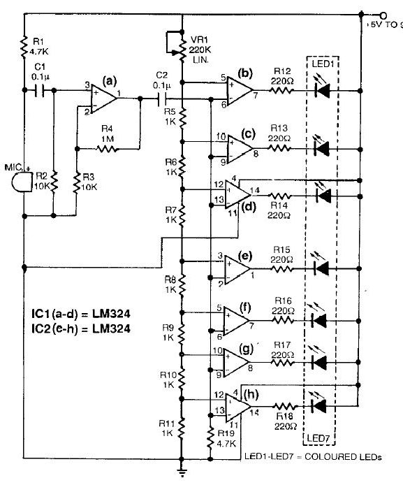
The sound level meter circuit is designed to measure sound intensity levels in various environments, such as recording studios or entertainment venues like discos. The circuit operates within a range of 70 dB to 120 dB, providing five distinct measurement domains that allow users to monitor sound levels effectively.
The core components of the circuit typically include a microphone sensor that converts sound waves into an electrical signal, an amplifier to enhance the signal strength, and an analog-to-digital converter (ADC) that translates the analog signal into a digital format for processing. Additionally, a microcontroller or a dedicated sound level meter IC may be employed to interpret the digital signal and display the sound level on an LED or LCD screen.
To enhance functionality, the circuit may also incorporate features such as peak hold, which captures the maximum sound level for a brief period, and an adjustable threshold that can be set to trigger alarms or notifications when sound levels exceed a predefined limit. Power supply considerations are crucial; the circuit can be powered by batteries or an external power source, ensuring portability and ease of use.
Overall, the sound level meter circuit serves as a vital tool for monitoring and controlling sound intensity, ensuring optimal audio experiences in various settings.This sound level meter circuit can be used to control the intensity of a sound recording or in a disco. It has 5 measurement domains between 70 and 120 dB;.. 🔗 External reference
Related Circuits
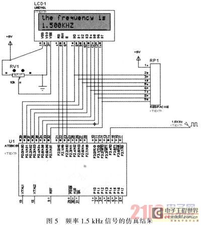
The primary function of the frequency counter is to measure the frequency and cycle of a signal. Its applications span a wide range, extending beyond simple instrument measurements to areas such as education, scientific research, high-precision instrument measurement, and...
The Wien-Bridge oscillator meets specific requirements due to the presence of a low-pass filter, a high-pass filter, and a 180-degree phase shift from the feedback networks connecting the input to the output. This configuration results in a total phase...
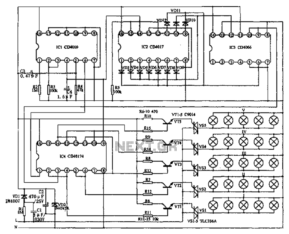
The circuit primarily consists of the NAND gate IC1 (CD4096), a counting/timing distribution circuit IC2 (CD4017), an analog electronic switch IC3 (CD4066), and a D flip-flop IC4 (CD40174), along with other components. The controller is capable of managing the...
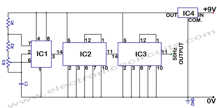
Accurate 50Hz Oscillator Circuit Using 555 and 7490. This circuit generates a 50Hz pulse. It consists of a 555 timer and two 7490 divide-by-ten counters. The circuit utilizes a 555 timer configured in astable mode to produce a square wave...
This electronic lie detector circuit project will provide two readings: one for challenging questions posed to the subject and another to indicate their emotional state. The electronic lie detector circuit operates on the principles of galvanic skin response (GSR) and...
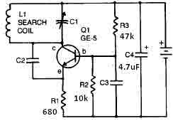
This metal detector circuit requires a power supply of 9 volts (DC) or a 9-volt battery. The circuit includes a variable capacitor C1 valued at 365 pF, a 100 pF silver mica capacitor C2, a 0.05 µF disc capacitor...