
TV Transmitter circuit diagram (VHF)
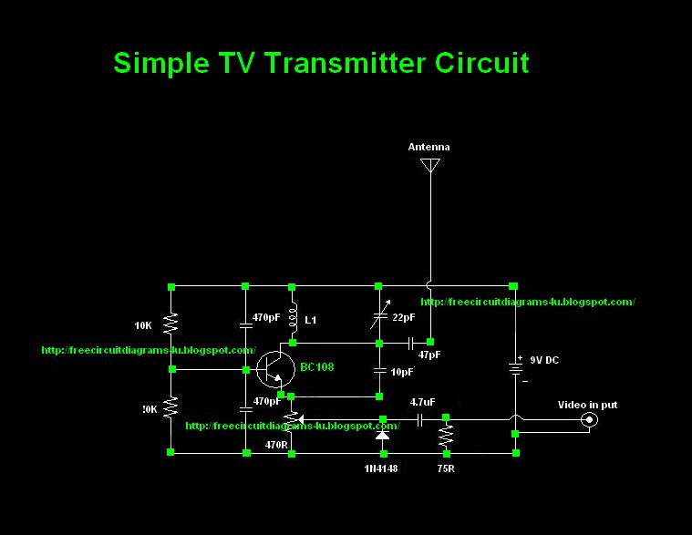
The TV transmitter circuit described is designed to operate effectively within a range of frequencies, allowing for versatile applications. The choice of the BC 108 transistor is significant due to its favorable characteristics for RF applications; however, alternatives like the BC337, 2N2222, and BC546 can also be employed without compromising performance. This flexibility in component selection aids in accessibility for builders who may not have the original transistor on hand.
The inductor L1 plays a crucial role in determining the operating frequency of the transmitter. The winding specifications are tailored to achieve specific frequency ranges: 6 turns for the lower band (60 - 80 MHz), 4 turns for the mid-band (150 - 180 MHz), and 2 turns for the upper band (180 - 200 MHz). The use of #24 enameled wire for winding ensures adequate inductance while maintaining a manageable size for the air former, which is essential for effective signal transmission.
The circuit's design emphasizes simplicity and functionality, making it suitable for hobbyists and those interested in exploring RF transmission. Proper assembly and tuning of the circuit will yield optimal performance, allowing users to transmit signals effectively over the stated distances. Additionally, the invitation for others to contribute their circuit designs fosters a collaborative environment, promoting knowledge sharing within the electronics community.Most of people ask TV transmitters. So Today I`m going to give you a very useful circuit diagram. By using this circuit you can send your signals 75m to 100m. This circuit diagram is not my own circuit one of my friends gave me this. I suppose you guys also can send your own circuit diagrams for us. Then we can publish them through our website. Here The y have used common transistor BC 108 If you are unable to find this transistor you can use equal transistors like Bc337 2n2222 Bc 546 # To make L1 wound 6 turns of #24 enameled wire on a 10mm air former for frequency 60 - 80 MHz For 150 - 180 MHz wound 4 turns and for 180 - 200MHz wound 2 turns. 🔗 External reference
Related Circuits
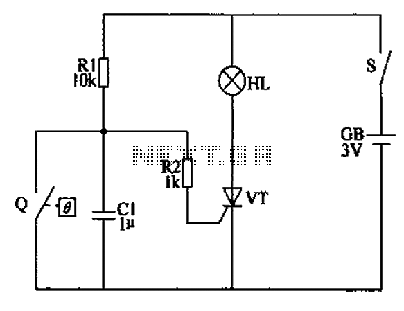
The automatic anti-frost crop controller circuit comprises an electric contact mercury thermometer (Q), a control circuit, ignition devices, and other components. The electric contact mercury thermometer features two platinum electrodes; one acts as a contact electrode inserted at the...
Bluetooth is an open wireless technology standard for exchanging data over short distances between fixed and mobile devices, utilizing short wavelength radio transmissions to create personal area networks (PANs) with high security. The Bluetooth baseband protocol combines circuit and...
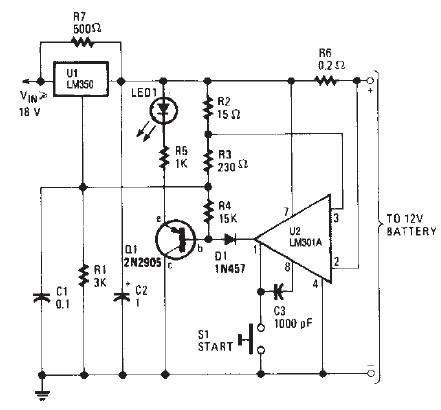
The LM350 car battery charger circuit is a high-performance device designed to efficiently charge gelled lead-acid batteries and automatically terminate the charging process once the battery reaches full charge. This circuit provides a charging current of 2A when the...
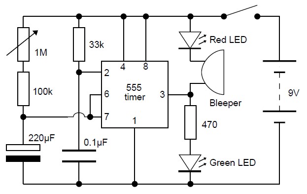
This adjustable analog timer circuit begins timing when it is activated. A green LED illuminates to indicate that the timing is in progress. Upon completion of the set time period, the green LED turns off, a red LED activates,...

A simple touch dimmer circuit diagram using the TT6061 IC, which is a touch control integrated circuit used for light dimmer circuits and lamp dimmer circuits. The touch dimmer circuit utilizing the TT6061 IC is designed to provide a user-friendly...
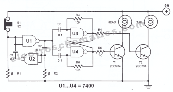
The principle utilized in this electronic head or tail circuit is straightforward: a multivibrator controls a flip-flop. The multivibrator oscillates as long as the button S1 is pressed, while the flip-flop toggles on and off at a frequency of...