
lm350 car battery charger circuit design

The LM350 car battery charger circuit utilizes an LM350 voltage regulator as its core component, which is known for its ability to maintain a stable output voltage and current. The circuit is designed to handle gelled lead-acid batteries, which require specific charging characteristics to ensure longevity and performance. The initial charging phase delivers a constant current of 2A, which is suitable for quickly replenishing the battery's charge.
As the battery voltage rises during the charging process, the current gradually decreases. This behavior is essential as it prevents the battery from being overcharged, which can lead to damage or reduced lifespan. Once the current falls to a threshold of 150 mA, the circuit transitions to a float charging mode, maintaining the battery at a safe voltage level without further increasing the charge.
The inclusion of transistor Q1 and LED1 provides a visual indication of the charging status, allowing users to easily monitor the process. The resistors in the circuit play critical roles in setting the current limits and ensuring the stability of the charging operation. Specifically, R2, R3, and R6 are 1-watt resistors that help manage the circuit's performance, while R7, rated at 5 watts, is capable of handling higher power dissipation.
The push-button switch serves as an interface for users to initiate the charging process, temporarily raising the output voltage to 14.5 V. This higher voltage is necessary to effectively charge the battery. As the battery approaches full charge, the circuit intelligently reduces the output voltage to around 12.5 V, ensuring that the battery is maintained in a charged state without the risk of overcharging.
Overall, the LM350 car battery charger circuit is a well-designed solution for efficiently charging gelled lead-acid batteries while incorporating safety features to protect the battery's health.This LM350 Car battery charger circuit project is a high performance charger that quickly charges gelled lead-acid batteries and turns off the charger process at full charge. This LM350 Car battery charger circuit will provide a charge current of 2A when the battery is nod fully charged, but as buttery voltage rise, current decreases.
When the current falls to 150 mA, the charger automatically switches to a lower float voltage to prevent the overcharging. When the charging process is finish the transistor Q1 make the LED1 to glow, to indicate the state of charging process.
The small value resistors R2, R3, R6 must be 1 watt resistors and R7 must be 5 watts resistors. When the push button switch is pushed, the output voltage of the charger goes to 14. 5 V and when the battery approaches to full charge, the charging current decreases and the output voltage is reduced to about 12. 5 V. 🔗 External reference
Related Circuits
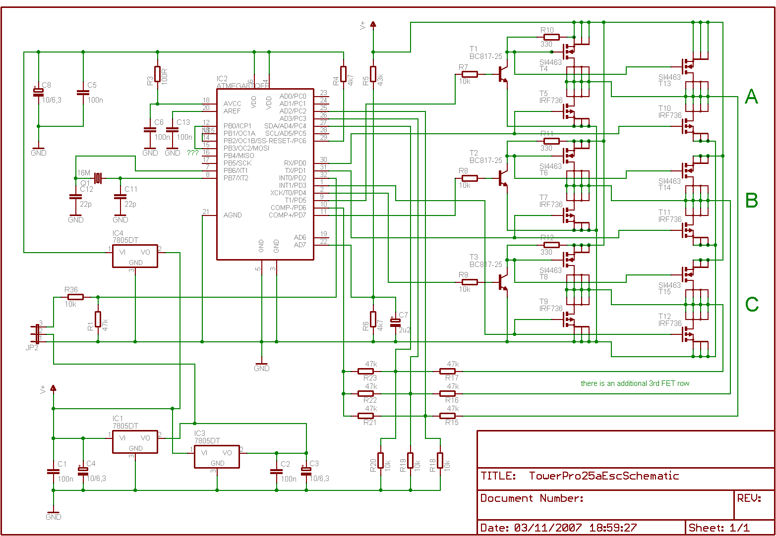
Is it feasible to eliminate the Electronic Speed Controllers (ESCs) from a multicopter configuration and substitute them with a single circuit board to control all the motors? The current setup consists of eight motors, each requiring an individual ESC,...
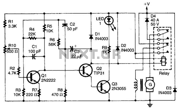
This regulator is designed to control a DC generator. In this configuration, one side of the field is grounded. Diode D4 prevents the battery from discharging through the generator and serves as a replacement for the mechanical cut-out relay....
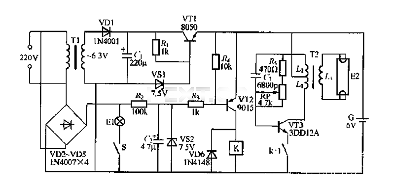
FIG. 284 illustrates a practical emergency power lighting system that activates automatically in the event of a sudden power outage. The fluorescent lights serve as emergency lighting. If the primary illumination lamp is turned off due to a power...
This simple circuit tests speakers, microphones, transformers, and voltage. It is essentially a very low-frequency oscillator that produces extremely short pulses. The sound produced is easy to hear and helps determine the precise direction it originates from, making it...
This circuit utilizes a relay to control a water pump, enabling automatic level management of a water reservoir or well. The shorter steel rod functions as the "water high" sensor, while the longer rod serves as the "water low"...
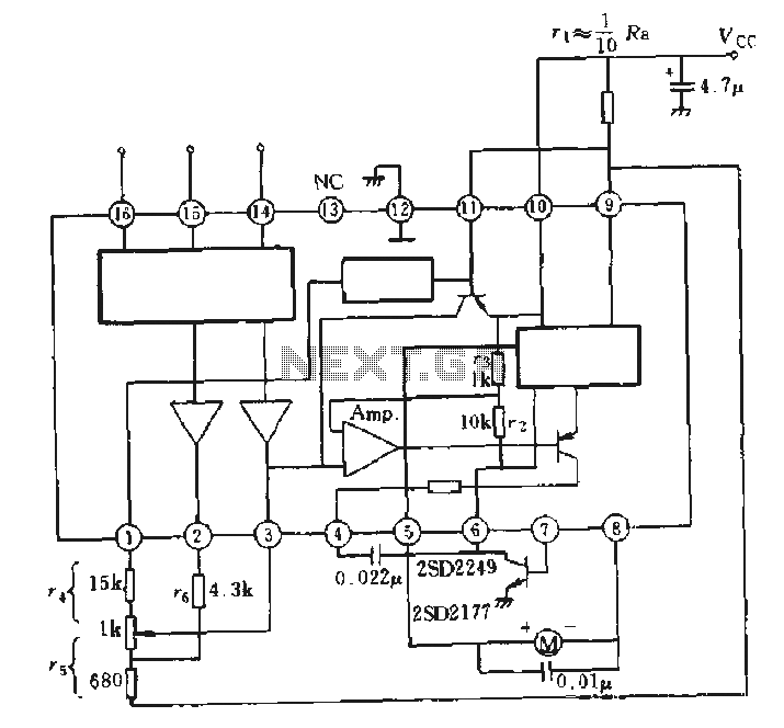
The AN6657 is a 16-pin dual in-line plastic package, while the AN6657S features a 16-pin dual flat plastic package. The speed control function operates with an internal H-bridge driver chip circuit, utilizing pins 5 and 8 for H-bridge driver...