
Triangle Wave Generator

The described circuit primarily functions as an inverting integrator, which is a fundamental component in analog signal processing. The operational amplifier used in this configuration is critical for its ability to amplify voltage differences. Initially, the op-amp's non-inverting input is set to a voltage slightly above ground, which allows it to amplify the input difference significantly. The output voltage swings to the positive power supply limit (15 V), which indicates that the circuit is in a charging state.
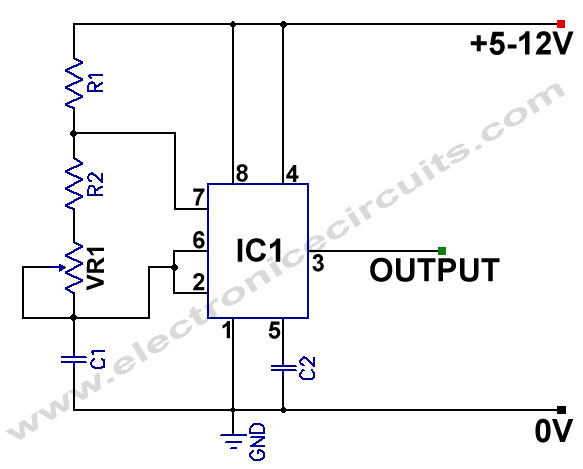
The integration process is facilitated by the feedback network formed by the resistors. The 10kΩ and 4kΩ resistors create a voltage divider that stabilizes the non-inverting input of the first op-amp. This configuration ensures that the input voltage to the op-amp is carefully controlled, allowing for predictable behavior as the integrator processes the input signal.
As the output of the integrator decreases, it does so at a constant rate, which is characteristic of integration in an analog circuit. The output voltage will continue to drop until the voltage at the non-inverting input reaches ground. At this point, the op-amp's output will switch polarity, causing the integrator to reverse its output direction. This transition effectively creates a triangular waveform, as the output voltage will rise and fall in a linear fashion.
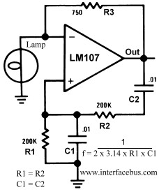
The cycle continues as the op-amp toggles between its output states, generating a continuous triangular waveform. This behavior is essential in various applications, including waveform generation and signal modulation. The precise values of the resistors can be adjusted to modify the integration rate and the frequency of the output waveform, providing flexibility in circuit design for specific applications.The second half of the circuit is an inverting integrator. The first op-amp starts with its two inputs in an unknown state; let`s say it starts with + slightly higher than (which is at ground). The op-amp greatly amplifies this difference, bringing its output to the op-amp`s positive power supply voltage, its maximum output (15 V in this case)
. With this positive input, the integrator`s output falls at a constant rate. The 10k and 4k resistors act as a voltage divider which put the first op-amp`s + input 4/14ths of the way from the second op-amp`s output to the first op-amp`s output. When this input reaches ground, then the first op-amp`s output switches polarity, and the integrator switches direction, forming the other half of the triangle.
When the first op-amp switches polarity again, a new cycle begins. 🔗 External reference
Related Circuits
This circuit generates speed pulses from the speed-dependent voltage spikes produced by commonly used types of PC power supply fans, which are superimposed. The circuit utilizes the voltage spikes generated by the fan's operation to create a series of speed...
This circuit generates a 10Hz sine wave using a minimal number of components, based on the specified component values. The active components are generic and can be substituted as needed. The passive component values determine the frequency and should...
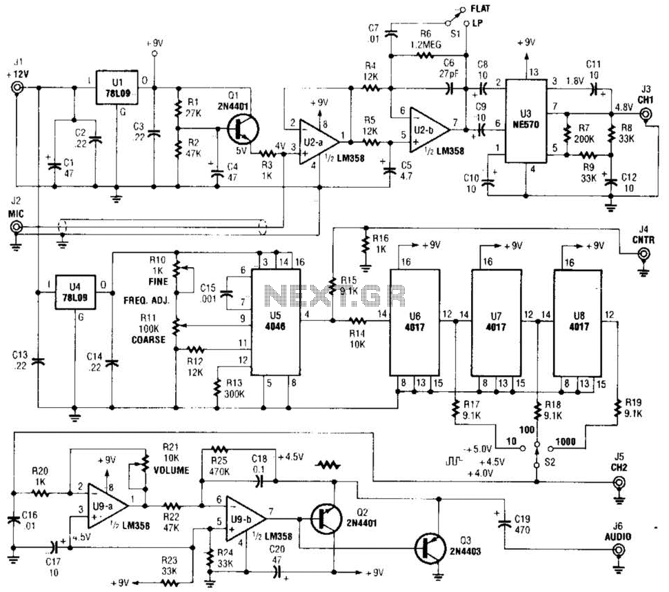
The precision audio frequency generator consists of several sub-circuits: an audio amplifier/filter circuit, an automatic level control, a variable voltage-controlled oscillator, a frequency divider circuit, an integrator, and an audio output amplifier. An electret microphone element is utilized to...
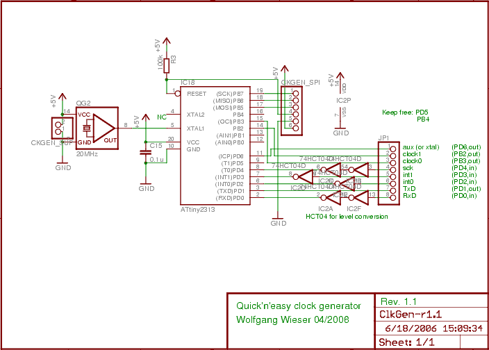
The design generates varying sampling clock write strobe pulses using an ATtiny2313 microcontroller from Atmel. For a 10MHz sampling clock, a 20MHz clock is required for the ATtiny2313, necessitating a power supply of 5V instead of 3.3V, which is...
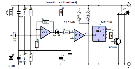
This electronic game simulates a one-arm bandit game, appealing to electronics hobbyists. When toggle switch S1 is in the 'run' position, all segments of the 7-segment displays (DIS1 through DIS3) illuminate. Upon switching S1 from 'run' to 'stop', the...
555 Variable Frequency Square Wave Generator. This simple 555 Variable Frequency Square Wave Generator produces a variable frequency output. The 555 Variable Frequency Square Wave Generator is a versatile circuit that utilizes the 555 timer IC to generate square wave...