
USB AVR In-System-Programmer (ISP)
")
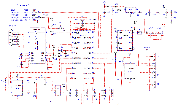
The circuit design for the modified AVR In-System-Programmer incorporates the FT232BM USB to serial converter, which acts as the bridge between the PC and the AVR microcontroller. The FT232BM chip provides the necessary serial communication capabilities and is connected to the ATtiny2313 microcontroller through a set of pins that facilitate UART communication. In this setup, the TX and RX pins of the FT232BM are directly connected to the corresponding RX and TX pins of the ATtiny2313, allowing for seamless data transfer.
The power supply for the ATtiny2313 is derived from the USB connection, ensuring that the programmer does not require an external power source. The S1 switch plays a crucial role in enabling or disabling the +5V supply to the target AVR, which can be particularly useful when programming multiple devices or when power management is a concern.
The use of a serial EEPROM (IC1) allows for the storage of customizable settings, which enhances the user experience by enabling the programmer to be identified with a user-friendly name. The EEPROM interface is connected to the FT232BM, allowing the chip to read and write settings as needed.
Additionally, the LED D1 provides a visual indication of data activity, flashing during transmission and reception, which aids in troubleshooting and confirms that the programmer is functioning correctly.
Overall, the design of this modified AVR In-System-Programmer is efficient and cost-effective, utilizing readily available components while ensuring compatibility with a wide range of AVR devices through the use of versatile programming software. The careful selection of components and firmware enhances the performance and usability of the programmer, making it a valuable tool for developers and hobbyists alike.Nowadays, USBis the most popular connection connection between PC and peripherals such as AVR programmers, printers, scanners etc. For that reason I had to modify my old serial AVR In-System-Programmer (ISP) to work with USB connection.
You can say, "use a USB to Serial adaptorto connect your AVR ISP with your PC". Yes, that could be a solution bu t itwould cost memoremoney than a singe FT232BM chipbecauseIhad to include an USB to RS232 adaptor and apower supply for myprogrammer. (almost ‚¬30). So, the solution was to replace the two transistors, that were used to adapt the RS-232 voltage levels to TTL voltage levels, with a USB to RS-232 chip such asFT-232BM.
Initially, I used the John Samperi`s firmware V3. 2 but afterwardsI found out the Klaus Leidinger`s firmware that was a little bit faster. So, I chose the second one firmware but I had to modify the source codeto work with 11. 0592MHz crystal instead of 7. 3724MHz that was initially designed because I couldn`t find this crystal in the market. This programmer worked perfect with AVRprog but then I found a software that could support much moreAVR devices than the AVRprog could program. This software is AvrOspII V5. 47. Following the schematic diagramthat I read in the FT232BM manual I made the connections between ATtiny2313 and FT232BM.
The FT232BM requires a few and ordinary components to work. When you connect this circuit to your PC you will see the message " a new hardware was found" and then the factory name of FT232BM. IC1 is a serial EEPROM that used to store user`s settings. So, you can rename this programmer to be appeared as "AVR In-System-Programmer" or "MyAVR programmer".
Furthermore, you can add the firmware version of your circuit. Of cource, you can bypass this component because it`s optional. I saw that the programmer works with orwithout this EEPROM. Anyway, FTDI suggests you to use this EEPROM. Led D1 flasheswhen data are transmitted or received by FT232BM. CN1 is a USB-B connector and CN2 is a 6-pin connector to your target AVR (it is connected to the AVR to be programmed). The S1 switch is used to supply your target circuit with +5V from the USB connector of your PC. In this case you won`t need any additional power supply for your target circuit. Consider that a single USB port can supply up to 500mA current. You should not exceed this current limitation including the current that needs your AVR programmer too.
Burn the ATtiny2313 withavr910_2313_v38c. hexfile. Do not forget to deselect the "Devide clock by 8 internaly" option and select the "Ext. Crystal Osc. 14CK + 65ms" option on fuses section of your AVR programming software. As I said before, you can configure your programmer to be appeared with the name you want. In this case, my programmer is appeared as "AVR In-System-Programmer" when I plug it in to the USB port. Note that if you change any information on this screen you should change the same information in the "FTDIBUS.
INF" and "FTDIPORT. INF" files. If you don`t makeany modification to the EEPROM and you have Windows XP SP2 or newer operating system, you won`t need any driver. All the necessary drivers are included in your operating system. The programming software that was chosen isAvrOspII V5. 47 (currently version) because it supports a lot of AVR devices and the author of this software Mike Henning is keep on writing new versions supporting new AVR devices.
You can see if there is a new AvrOspII version available Here. 🔗 External reference
Related Circuits
Even including labor, the actual cost of purchasing, stocking, assembly, assembly errors, more expensive PCBs (with additional holes and larger sizes), and the increased difficulty in tuning would likely result in significantly higher expenses. The analysis of costs associated with...

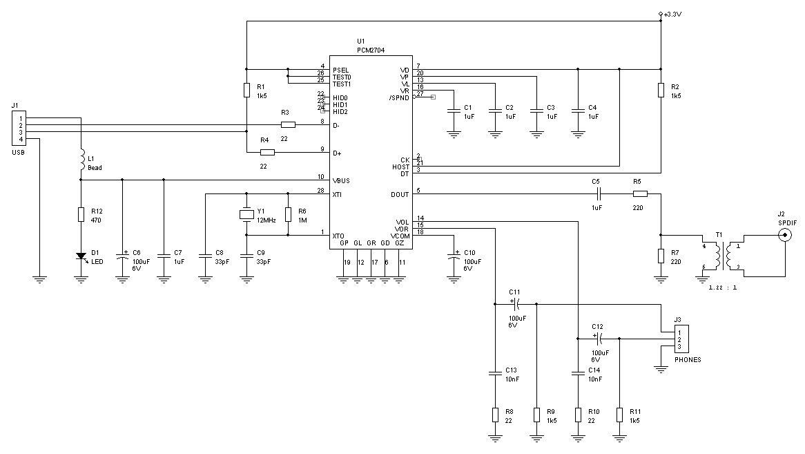
If you use great IC PCM2702 from BURR BROWN / Texas Instruments you can create a fully functional USB sound card. This sound card can be powered from USB port and has one stereo output. You don’t need to...
Is there a source for a schematic for a USB to SPDIF converter, similar to those offered by Empirical Audio? The concept is appealing, but the price of $500 is quite high. A USB to SPDIF converter is a device...
The core of this construction is 16-Bit Stereo Digital-To-Analog Converter with USB interface PCM2702. PCM2702 needs only a few additional parts to work. The schematic is not complex. The sound card can be powered directly from the USB port...
The Atmel AVR series consists of high-quality microcontrollers featuring a comprehensive instruction set, which has led to the development of numerous effective compilers, eliminating the need to learn assembly language. One notable compiler is the BASCOM/AVR from MCS Electronics,...
The USB charger power supply is designed for use in MP3 and MP4 chargers. It accepts an input of AC 160-240V at 50/60Hz and has a rated output of DC 5V at 250mA. For applications requiring a long-term higher...