
USB to SPDIF Converter

A USB to SPDIF converter is a device that enables the transmission of digital audio signals from a USB source to a SPDIF output, commonly used in high-fidelity audio systems. Such converters are essential for connecting computers or other USB audio sources to digital audio receivers or DACs that accept SPDIF input.
The core components of a USB to SPDIF converter typically include a USB interface chip, a digital audio processor, and a SPDIF output stage. The USB interface chip, such as the PCM2706 or similar, handles the USB audio data transfer. The digital audio processor converts the received USB audio data into a format suitable for SPDIF transmission. This processor may include a sample rate converter to ensure compatibility with various audio formats.
For the SPDIF output stage, a digital signal transmitter, such as the CS8406, is often employed. This component is responsible for generating the SPDIF signal, which can be transmitted over coaxial or optical cables. Power supply considerations are also critical; the circuit typically requires a regulated power source to ensure stable operation.
In designing a schematic for a USB to SPDIF converter, the following key elements should be included:
1. **Power Supply Circuit**: A stable power supply circuit that provides the necessary voltage and current for the components.
2. **USB Input Circuit**: A USB connector and associated circuitry to interface with the USB source.
3. **Digital Audio Processing Circuit**: The digital audio processor, which may include filtering and conversion components.
4. **SPDIF Output Circuit**: The SPDIF transmitter and necessary output connectors (coaxial or optical).
5. **Grounding and Shielding Considerations**: Proper grounding techniques and shielding to minimize noise and interference in the audio signal.
By following these guidelines and utilizing appropriate components, a functional USB to SPDIF converter schematic can be developed, providing a cost-effective solution for high-quality digital audio transmission.Does anyone know where I can get a schematic for a USB to SPDIF converter, like the ones from empirical audio. Thanks!!! I like their concept but $500 .. 🔗 External reference
Related Circuits
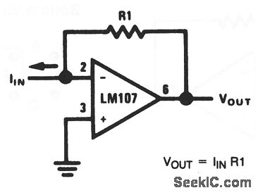
This basic circuit feeds the input current directly into the summing node (pin 2), causing the op-amp output to adjust and extract the same current from the summing node through resistor R1. The scale factor of the circuit is...

A portable battery-powered USB charger circuit or schematic utilizing the IC LM7805. The circuit requires only a few components. The portable battery-powered USB charger circuit based on the LM7805 voltage regulator is designed to convert a higher voltage from a...
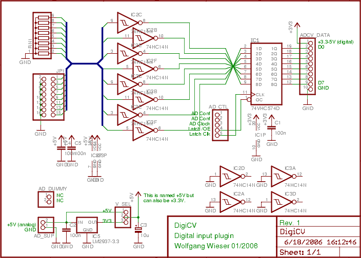
The digital input board features eight distinct digital inputs available on connector JP1. Each input is equipped with separate pull-down resistors (RN1, with a recommended value of 1 MΩ) and a Schmitt-trigger. To prevent damage from improper input voltages,...
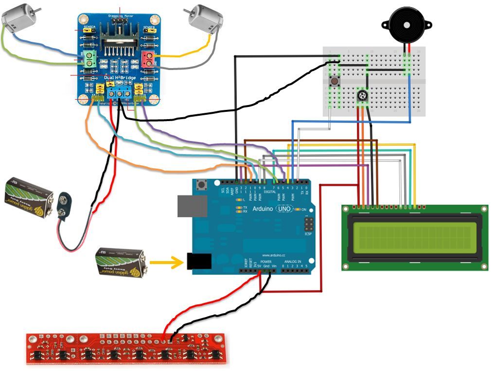
If the robot is positioned on the black line, it will continue moving forward. However, if it veers off the line and enters a white area, it will assess whether to correct its path to the left or right,...
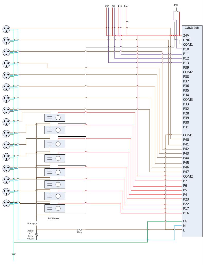
This is the circuit diagram for the Comfile CUSB-36R Programmed Christmas Lights. If it is difficult to read, please contact me via email at [email protected], and I will provide a more detailed schematic. The Comfile CUSB-36R can either drive...
The circuit diagram depicts a design that achieves 0.25% exponential conformity over a frequency range of 20 Hz to 15 kHz using a single LM392 and an LM3045 transistor array. The exponential function is generated by Q1, whose collector...