
automatic power factor controller using microcontroller
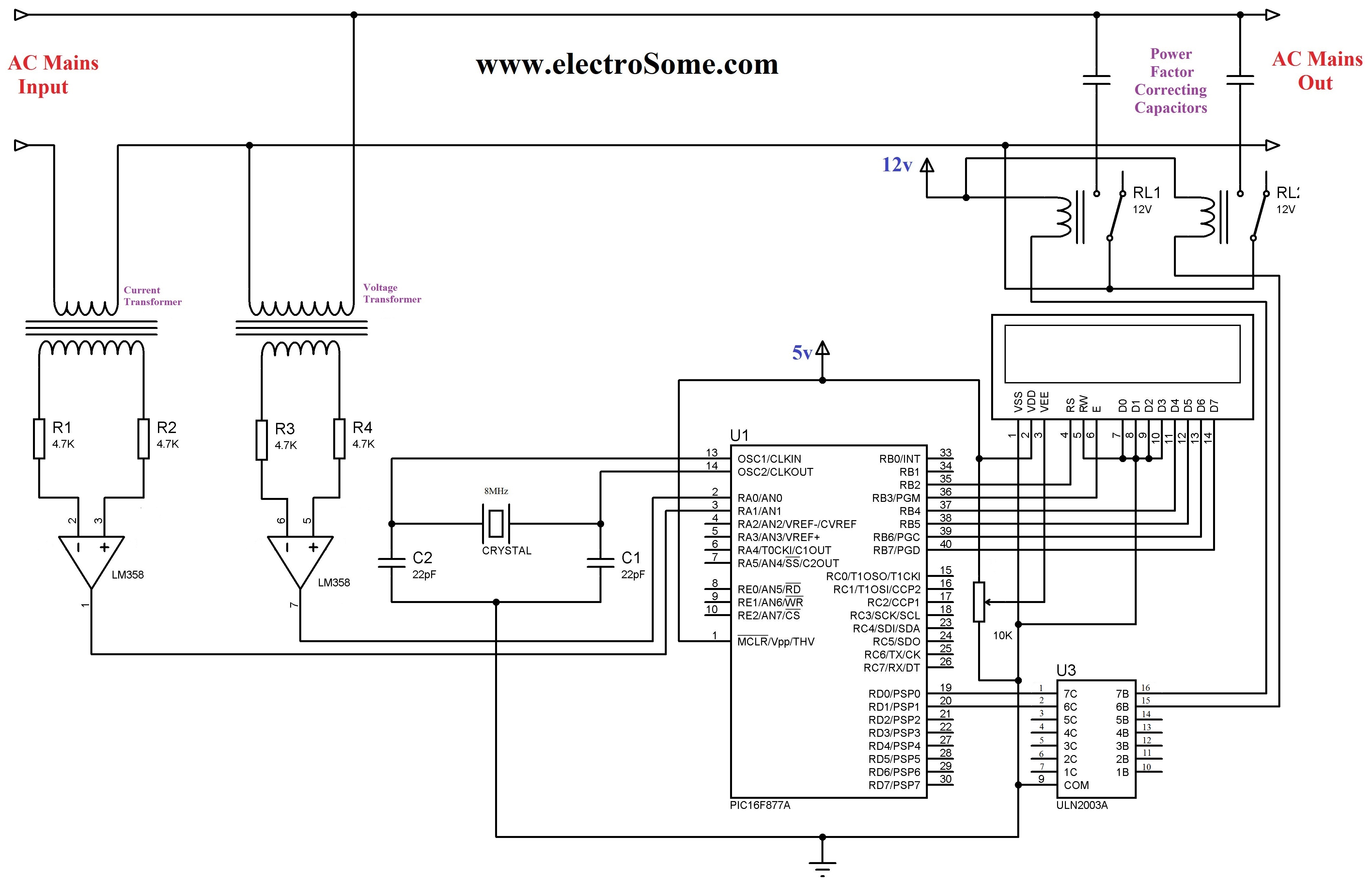
The LCD module connections are established as follows: the RS pin is connected to RB4, the EN pin to RB5, and data pins D4 to D7 are connected to RB0 to RB3 respectively. The direction of these pins is defined in the code, ensuring proper communication between the microcontroller and the LCD.
The function `powerFactor()` calculates the current power factor using the Timer 1 module of the PIC 16F877A. The algorithm captures the time intervals between zero crossings of the current and voltage waveforms, calculating the power factor based on these measurements. The main program continuously reads the power factor, averaging multiple readings to mitigate fluctuations. It displays the power factor on the LCD and controls the relay based on the calculated value, ensuring the power factor remains within acceptable limits for efficient operation.
The implementation utilizes various configurations of the microcontroller's ports to manage input and output effectively, ensuring a robust design for automatic power factor correction in real-time applications.The 230 V, 50 Hz is step downed using voltage transformer and current transformer is used to extract the waveforms of current. The output of the voltage transformer is proportional to the voltage across the load and output of current transformer is proportional to the currentG‚throughG‚the load.
These waveforms are fed to Voltage Comparators const ructedG‚usingG‚LM358G‚op-amp. Since it is a zero crossing detector, its outputG‚changesG‚during zero crossing of the current and voltage waveforms. These outputs are fed to the PIC which does the further power factor calculations. PIC 16F877A microcontroller is the heart of this Automatic Power Factor Controller, it find, displays andG‚controlsG‚the Power Factor.
To correct power factor, first we need to find the current power factor. It can be find by taking tangent of ratio of time between zero crossing of current and voltageG‚waveformsG‚and two successive zero crossing of voltage waveform. Then it displays the calculated power factor in the 16G—2 LCD Display andG‚switchesG‚ON the capacitors if required.
When load is connected the power factor is calculated by the PIC microcontroller. If the calculated power factor is less than 0. 9 then the relay switches on the capacitor. The relays are switched using ULN2003 which is basically a driver IC. ULN2003 consists of seven DARLINGTON PAIRS. The current lead in capacitor compensates the corresponding current lag which is usually present in loads. Hence the phase difference between the current and voltage will be reduced. Power Factor Correcting capacitor connected parallel to load through relay, if the relay is energized by microcontroller it will connect G‚the capacitor parallel with load, if relay deenergized it will remove the capacitor from the load.
When the resistive load is on the power factor will be near to unity so the microcontrollerG‚doesn`tG‚energize the relay coil. When the inductive load is on the power factor decrease now the microcontroller energize the relay coil in order to compensate the excessive reactive power.
Hence according to the load the power factor is corrected. //LCD Module Connections sbit LCD_RS at RB4_bit; sbit LCD_EN at RB5_bit; sbit LCD_D4 at RB0_bit; sbit LCD_D5 at RB1_bit; sbit LCD_D6 at RB2_bit; sbit LCD_D7 at RB3_bit; sbit LCD_RS_Direction at TRISB4_bit; sbit LCD_EN_Direction at TRISB5_bit; sbit LCD_D4_Direction at TRISB0_bit; sbit LCD_D5_Direction at TRISB1_bit; sbit LCD_D6_Direction at TRISB2_bit; sbit LCD_D7_Direction at TRISB3_bit; //End LCD Module Connections int powerFactor() { int a=0, b=0, t=0, x=0; float tm, pf; TMR1L=0; TMR1H=0; do { if(PORTA. F0 = 1) T1CON. F0 = 1; else if(PORTA. F0 = 0 && T1CON. F0 = 1) { T1CON. F0 = 0; break; } }while(1); a = (TMR1L | (TMR1H<<8) * 2; TMR1L=0; TMR1H=0; do { if(PORTA. F0 = 1) { T1CON. F0=1; if(PORTA. F1=1) { T1CON. F0=0; break; } } }while(1); b = TMR1L | (TMR1H<<8); tm = (float)b/a; pf = cos(tm*2*3. 14); x=abs(ceil(pf*100); return x; } void main() { char c[]="0. 00"; int a, b, d, x, f, e; float tm, pf; Lcd_Init(); Lcd_Cmd(_LCD_CURSOR_OFF); // Cursor off ADCON1 = 0x08; // To configure PORTA pins as digital TRISA.
F0 = 1; // Makes First pin of PORTA as input TRISA. F1 = 1; //Makes Second pin of PORTA as input TRISD. F0 = 0; //Makes Fist pin of PORTD as output TRISD. F1 = 0; //Makes Second pin of PORTD as output while(1) { a = powerFactor(); Delay_us(50); b = powerFactor(); Delay_us(50); d = powerFactor(); Delay_us(50); e = powerFactor(); Delay_us(50); f = powerFactor(); x = (a+b+d+f+e)/5; c[3]=x%10 + 0x30; x=x/10; c[2]=x%10 + 0x30; x=x/10; c[0]=x%10 + 0x30; Lcd_Out(1, 1, "Power Factor"); Lcd_Out(2, 1, c); if(x<90) { PORTD. F0 = 1; PORTD. F0 = 1; Delay_ms(2000); } else { PORTD. F0 = 0; PORTD. F0 = 0; } Delay_ms(250); } } The function powerFactor() will find the current power factor by using the Timer 1 module of PIC 16F877a.
Power Factor may be fluctuating, so to avoid it we will find power facto 🔗 External reference
Related Circuits
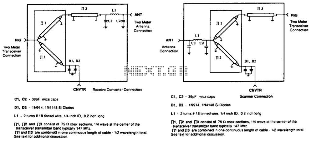
A pair of diodes and a quarter-wave transmission line are utilized as an automatic TR switch. D1 and D2 conduct during transmit periods, short-circuiting the scanner input. In this mode, the quarter-wave line appears as an open circuit. In...
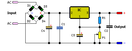
The simple method to power your projects is illustrated in the circuit diagram of a regulated power supply. This compact power supply delivers a stable voltage. This regulated power supply circuit is designed to convert an unregulated input voltage into...
This 555 timer circuit activates a relay upon pressing a button. The threshold and trigger inputs, pins 2 and 6, are maintained at half the supply voltage by two 10K resistors. When the output is high, a capacitor charges...
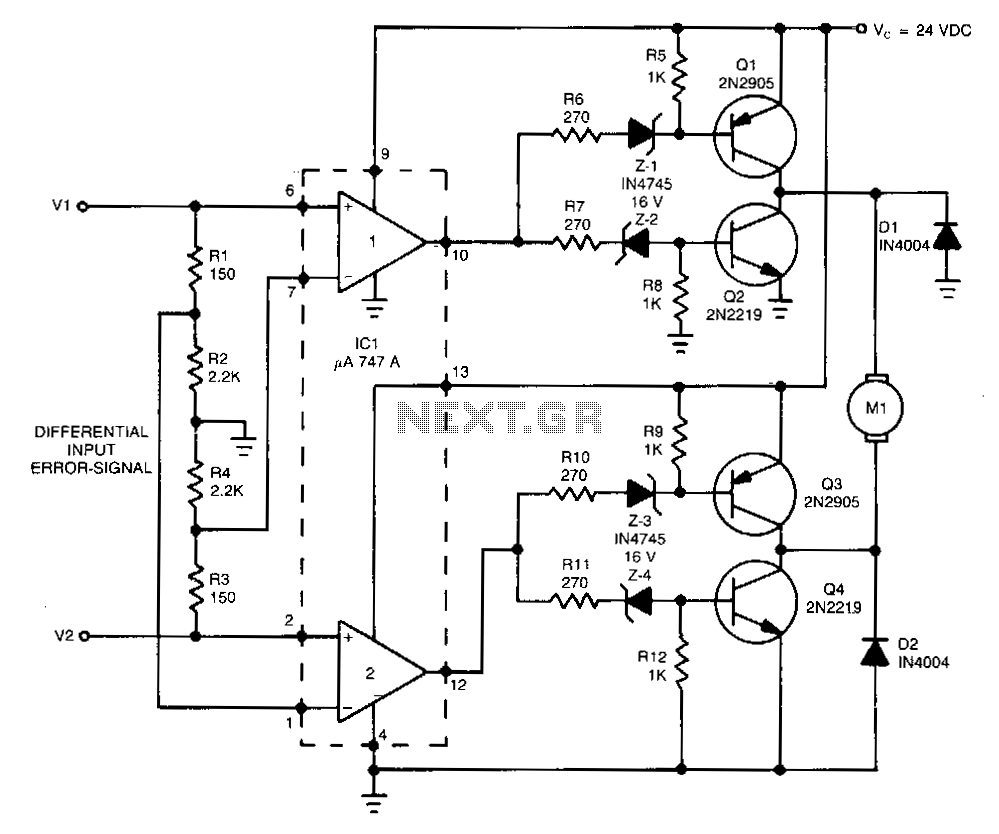
This high-performance switching controller for a low-power DC servo motor utilizes a symmetrical complementary-transistor bridge. The bridge functions as a reversing switch between the motor and a single-ended power supply. Because the transistors operate in a fully on or...
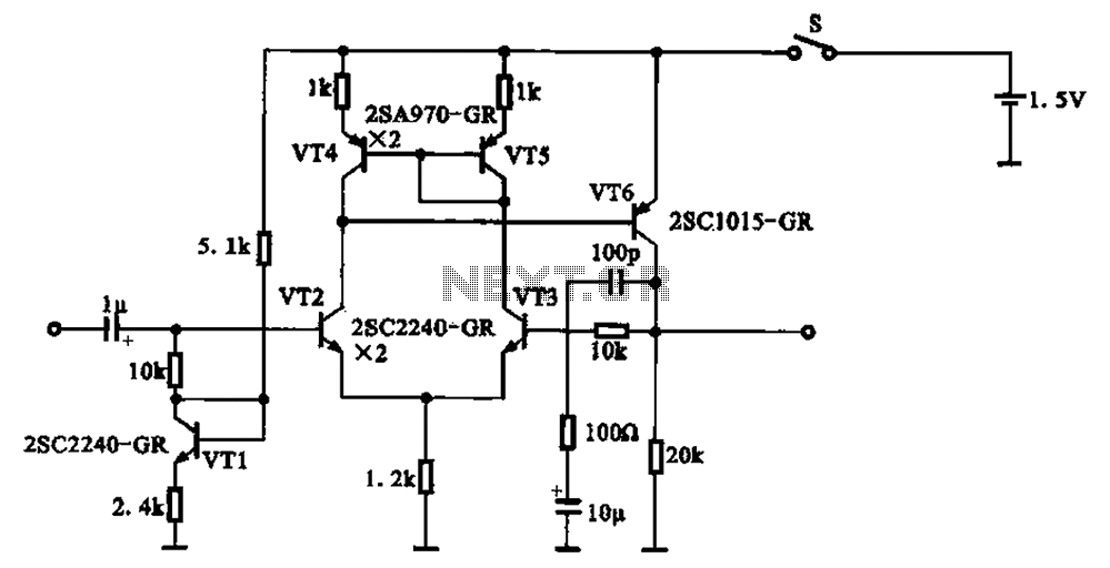
A 1.5V-powered microphone signal amplifying circuit is designed with a power supply for the microphone signal amplification. The circuit primarily consists of a differential amplifier formed by transistors VT2 and VT3. Additionally, VT6 functions as a common emitter voltage...
The controller uses one or more ordinary silicon diodes as a sensor, and uses a cheap opamp as the amplifier. I designed this circuit to use 12V computer fans, as these are now very easy to get cheaply. These...