
relay toggle circuit using a 555 timer

The described 555 timer circuit operates in a bistable mode, utilizing the versatile 555 timer IC, which is widely employed in timing applications. The relay serves as an output device that can control higher voltage or current loads, making it suitable for various automation tasks.
In this configuration, the two 10K resistors connected to pins 2 and 6 ensure that both inputs are biased to half the supply voltage, creating a stable reference point. This configuration allows the timer to respond to changes in voltage levels effectively. The capacitor, when charged, stores energy and influences the state of the output pin (pin 3) based on the voltage levels at the trigger and threshold inputs.
Upon pressing the button, the capacitor discharges, causing a momentary drop in voltage at pins 2 and 6. This drop triggers the 555 timer to switch its output state. If the output was previously low, it will switch to high, energizing the relay and allowing current to flow through its coil. The relay contacts can then close, completing a separate circuit and powering connected devices.
When the output transitions from high to low, the capacitor begins to charge again through the 100K resistor, which determines the timing characteristics of the circuit. The discharge process ensures that the relay remains in its activated state only for a brief period, providing a controlled response to the button press. This timing can be adjusted by changing the capacitor value or the resistance of the charging resistor, allowing for customization of the circuit's operational parameters.
In summary, this 555 timer relay circuit effectively demonstrates the principles of timing and control in electronics, showcasing how simple components can be combined to create useful applications in automation and control systems.This 555 timer circuit toggles a relay when a button is pressed. Pins 2 and 6, the threshold and trigger inputs, are held at 1/2 the supply voltage by the two 10K resistors. When the output is high, the capacitor charges through the 100K resistor, and discharges when the output is low.
When the button is pressed, the capacitor voltage is applied to pins 2 and 6 which causes the output to change to the opposite state.. 🔗 External reference
Related Circuits
This is an audio power amplifier that delivers 40 W at 8 ohms in Class A operation. The power transistors are continuously active, enabling a substantial current to flow. The audio power amplifier described operates in Class A mode, which...
The Over-the-Top type of operational amplifier is ideal for use as a current sense for battery charger applications. The design described here can be used. The Over-the-Top operational amplifier (op-amp) is specifically designed for applications requiring precise current sensing, particularly...
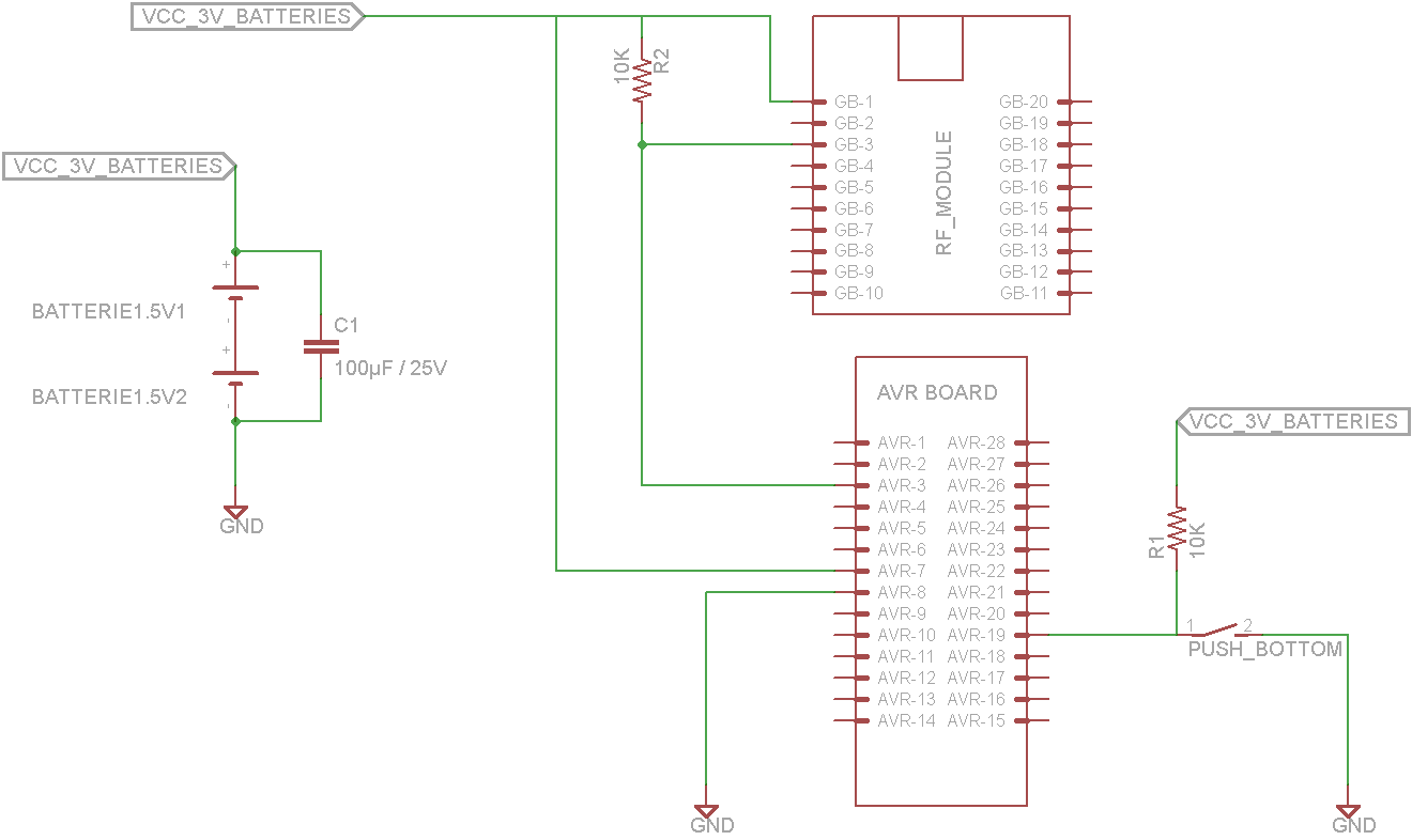
This tutorial demonstrates concepts for creating a lamp with dual actuation. The lamp can be controlled through a parallel switch or by a relay that is managed using an RF module based on the ZigBee protocol (IEEE 802.15.4). The...
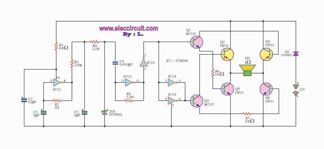
This is a simple siren sound generator with high power output and significant noise levels. The circuit utilizes digital integrated circuits (ICs), specifically the CD4046, in an inverter configuration along with four transistors to increase the current output to...
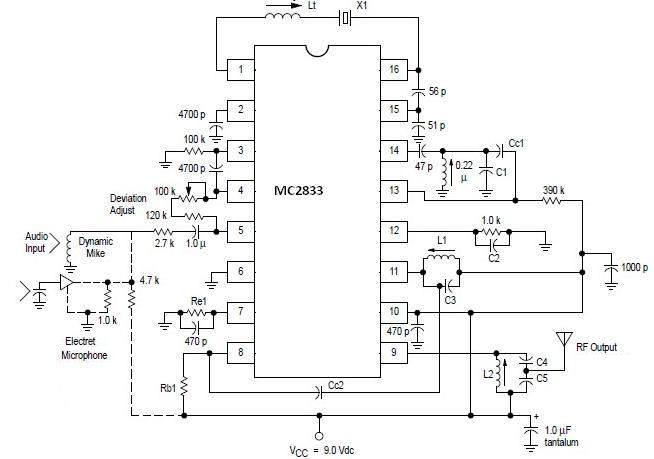
A simple FM transmitter circuit can be designed using the MC2833 integrated circuit, which is intended for cordless telephone and FM communication applications. This circuit includes a microphone amplifier, a voltage-controlled oscillator, and two auxiliary transistors. The final output...
The liquid level controller circuit comprises a power supply circuit and a level detection control circuit, as illustrated in the accompanying chart. The power supply circuit includes a power switch (S1), a power transformer (T), bridge rectifiers (UR1, UR2),...