
Motor Fan heat controller

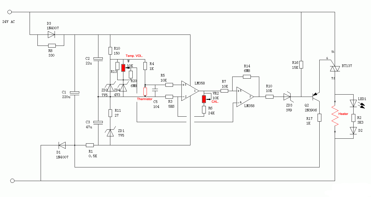
The described circuit utilizes silicon diodes as temperature sensors, which exhibit a predictable forward voltage drop that varies with temperature. The operational amplifier (op-amp) serves as a comparator, amplifying the small voltage signal produced by the diodes to a level sufficient to control a power transistor. The circuit is powered by a 12V supply, suitable for driving standard computer fans that typically consume around 200mA.
The BD140 transistor is employed as a switch, capable of handling up to 1A of current, making it suitable for controlling the fan operation. Its characteristics allow for effective switching with minimal heat generation, given the low power requirements of the fan. The circuit design enables the use of various substitute transistors, provided they meet the necessary current and voltage specifications.
A variable resistor, designated as VR1, is incorporated into the circuit to set the desired temperature threshold. The operational amplifier is initially adjusted to stabilize at the normal operating temperature. As the temperature rises above this threshold, the op-amp output activates the transistor, which in turn powers the fan, providing cooling. The fan will continue to operate until the temperature drops back to the set point, at which point the circuit will deactivate the fan.
This feedback mechanism ensures that the fan operates only when necessary, enhancing energy efficiency and prolonging the lifespan of the components. The simplicity of the design, combined with the availability of parts, makes this circuit an effective solution for temperature control in various applications.The controller uses one or more ordinary silicon diodes as a sensor, and uses a cheap opamp as the amplifier. I designed this circuit to use 12V computer fans, as these are now very easy to get cheaply. These fans typically draw about 200mA when running, so a small power transistor will be fine as the switch.
I used a BD140 (1A, 6.5W), but almost anything you have to hand will work just as well. The temperature is set with VR1. Operate the amp until the normal temperature is reached, then adjust VR1 until the fan starts. Then back off very slowly until the fan stops again. Any increase over the normal temperature will start the fan, and promptly 🔗 External reference
Related Circuits
The sensor on the clone soldering station exhibits low resistance, while the replacement heater has a resistance of 45 Ohms. There is a query regarding the availability of clone heaters or the possibility of modifying the station to accommodate...
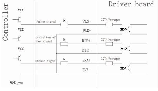
Connection of a drive and a two-phase hybrid stepper motor using a four-wire system, with the motor windings configured in both parallel and series connections. This method allows for high-speed performance, although it requires a large drive current (1.73...
Any stepper motor can be utilized as a generator. Unlike other types of generators, a stepper motor generates a significant induced voltage even at low rotational speeds. A stepper motor operates by converting electrical energy into mechanical motion through a...
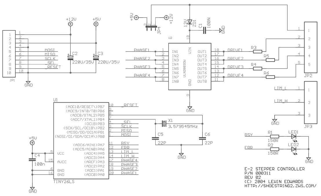
Stepper motors are beneficial for low-speed, intermediate-torque drive and positioning applications, especially where precise sub-revolution rotor position control is required. These motors are frequently utilized to drive the reels of electromechanical slot machines, position floppy disk drive heads, operate...
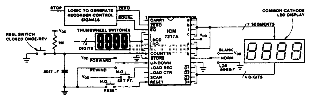
This circuit illustrates various applications of up/down counting for monitoring dimensional position. In the tape recorder application, the LOAD REGISTER, EQUAL, and ZERO outputs are utilized to control the recorder. To ensure the recorder stops at a specific point...
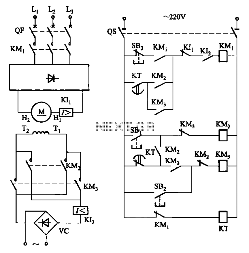
The circuit depicted in Figure 3-193 illustrates a separately excited DC motor. The brake circuit is not activated; therefore, positive reversals occur alternately using a delay action relay, ensuring that the motor reverses direction after coming to a stop. The...