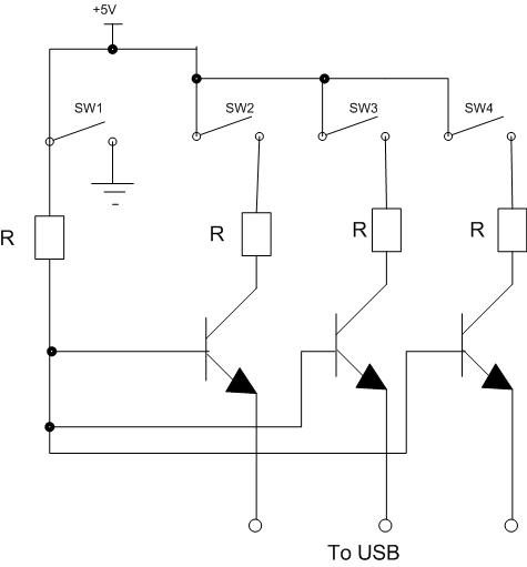
basic circuit diagram design

Four switches will be connected to a USB joystick board. The USB board has +5V and ground connections and emulates a button press.
The circuit involves interfacing four mechanical switches with a USB joystick interface. The USB joystick board typically operates at a voltage of +5V, which is standard for USB-powered devices. Each switch will be connected to a digital input pin on the joystick board.
To achieve this, the following steps should be taken:
1. **Power Supply**: Connect the +5V output from the USB joystick board to one terminal of each switch. The ground connection from the USB board should be connected to the common ground of the circuit.
2. **Switch Connections**: The other terminal of each switch should be connected to a separate digital input pin on the joystick board. When a switch is pressed, it will complete the circuit, allowing current to flow from the +5V through the switch to the input pin, simulating a button press.
3. **Pull-Down Resistors**: To ensure that the input pins read a stable LOW state when the switches are not pressed, pull-down resistors (typically 10kΩ) should be connected from each input pin to ground. This configuration prevents floating inputs, which can lead to erratic behavior.
4. **Debouncing**: Mechanical switches can produce noise when pressed or released, leading to multiple signals being registered. To mitigate this, a debouncing circuit can be implemented either in hardware using an RC filter or in software by programming the joystick board to ignore rapid state changes.
5. **Testing**: Once the connections are made, the circuit should be tested by pressing each switch and observing the corresponding output on the joystick board. This can be done using a computer or a microcontroller that can read USB joystick inputs.
This setup allows for a straightforward and effective way to utilize mechanical switches as input devices for various applications, enhancing user interaction with USB-compatible systems.Hi! I have a 4 switches that I`m goin to connect to a USB joystick board. The USB board has +5V and ground connections, and emulate a button press on.. 🔗 External reference


