
IC OCL power amplifier circuit

The OCL (Output Capacitor-Less) power amplifier circuit is designed to provide high-quality audio amplification while eliminating the need for output coupling capacitors. This feature enhances the overall efficiency of the circuit, allowing for a more compact design with fewer components. The integrated circuit IC1 serves as the core of the amplifier, which typically includes multiple transistors configured to handle both the voltage and current requirements of the output stage.
The internal configuration of IC1 closely resembles that of OTL (Output Transformer-Less) power amplifier circuits, which also prioritize efficiency and sound quality. In OCL designs, the output stage is directly connected to the load (such as speakers) without the use of transformers, allowing for a wider frequency response and reduced distortion.
In the OCL configuration, the circuit may employ feedback mechanisms to stabilize gain and improve linearity. The biasing of the transistors is crucial, as it determines the operating point and can significantly impact the performance characteristics of the amplifier, such as thermal stability and distortion levels.
The power supply requirements for an OCL amplifier typically involve a dual power supply, providing both positive and negative voltages to accommodate the AC signal swing. Careful attention must be paid to the power supply decoupling to minimize noise and ensure stable operation.
Overall, the OCL power amplifier circuit is a sophisticated solution for audio amplification, combining the benefits of integrated circuit technology with the high performance of advanced amplifier design principles.FIG OCL power amplifier circuit is an integrated circuit. Circuit IC1 is an integrated circuit, its internal circuit configuration is substantially similar to the integrated ci rcuit OTL power amplifier circuits.
Related Circuits
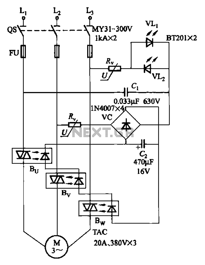
The circuit depicted in Figure 3-93 is integrated with an optical phase sequence protection relay. The circuit in question is designed to provide phase sequence protection using an optical relay mechanism. Optical phase sequence protection relays are crucial in applications...
Touch the sensor of the alarm with your finger, and it starts beeping. It continues for a period and then stops. Touching it again will activate the beeping once more. This description outlines a basic touch-activated alarm system. The...
This is a highly sensitive envelope detector designed for AM radio applications. The circuit, illustrated in Figure 1, enables linear detection of weak signals with a modulation depth of 80-85%. The first stage (VT1) functions as a common-emitter amplifier...
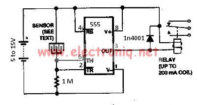
The water sensor circuit utilizes a 555 timer circuit along with common electronic components. It consists of two metal electrodes positioned closely enough that a drop of water can create a conductive bridge between them. If the water is...
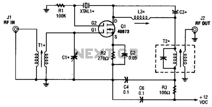
The second gate (G2) of a MOSFET can be utilized to integrate a crystal oscillator within the same stage as a frequency mixer. While this technique is common in tube technology, it is rarely implemented in dual-gate MOSFET circuits....
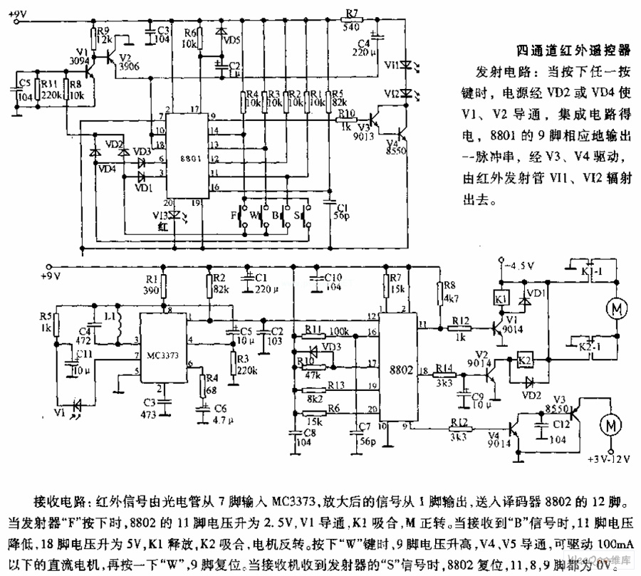
The receiving circuit involves an infrared signal being input to the MC3373 from pin 7 via a phototube. The amplified signal is output from pin 1 and sent to pin 12 of the decoder 8802. When the transmitter F...