
battery backup circuit

The two-diode selector circuit is an efficient solution for applications requiring automatic switching between power sources while ensuring optimal performance and reliability. The use of Schottky diodes is advantageous due to their low forward voltage drop and rapid switching capabilities, which minimize power loss and enhance circuit responsiveness.
In this configuration, when the primary voltage source is present and exceeds the turn-on voltage of the diodes, the circuit allows current to flow through the selected diode, powering the load. If the primary source fails or drops below the necessary voltage, the second diode can take over, ensuring continuous power supply.
The inclusion of a PNP transistor in the circuit serves to manage the flow of current effectively, preventing reverse current from the load back into the power sources. The design also accounts for the voltage drop across the diodes, which is critical in low-voltage applications where even minor losses can impact performance.
For applications that require flexibility in power source selection, the complementary FETs can be employed as an alternative to diodes. This approach can provide improved efficiency and is particularly suitable for higher power applications, although it necessitates careful consideration of the voltage levels between the power sources.
The schematic's power source switching section demonstrates a practical implementation of this concept, allowing the circuit to switch seamlessly between different voltage levels (e.g., +5V and +3V) based on availability. This feature is essential for devices like LCD backlight drivers, where consistent power supply is crucial for operation.
Overall, this two-diode selector circuit design is well-suited for applications requiring reliable power management with minimal losses, making it a valuable addition to low-power electronic systems.A 2 diode selector circuit if your primary voltage source is greater than the diodes turn on voltage and the input voltage of the second diode. Schottky diodes are recommended for both their low lower turn on voltage (typically 0. 4v) and high switching speed. You can use a 2 diode selector circuit if your primary voltage source is grea ter than the diodes turn on voltage and the input voltage of the second diode. Schottky diodes are recommended for both their low lower turn on voltage (typically 0. 4v) and high switching speed. Yes provided your voltages are all within the range the transistor can handle. I think the attached circuit would work. I`ve used something like this in a recent design and now the main and backup voltages can be equal. The transistor in the diagram is a PNP. Diodes have a voltage drop that needs to be accounted for. Another way to do it is with complementary FETs. A nice example is in the power source switching used here (the part of the schematic labeled "Power" which switches between +5v and +3v sources): Of course, the two weaknesses here are 1) these are low-power parts (intended for extremely low current device), and 2) it relies on the battery backup power source having a lower voltage than the external power source. Diodes have a voltage drop that needs to be accounted for. Another way to do it is with complementary FETs. A nice example is in the power source switching used here (the part of the schematic labeled "Power" which switches between +5v and +3v sources): Of course, the two weaknesses here are 1) these are low-power parts (intended for extremely low current device), and 2) it relies on the battery backup power source having a lower voltage than the external power source.
Left out a diode. Here is a circuit I`m using for switching between a battery and adapter (power pack to you aussies) for input to a lcd backlight driver. It employs a PNP mosfet to prevent current from being drawn from the battery when there is a voltage (provided by the adapter) present on the Gate.
🔗 External reference
Related Circuits
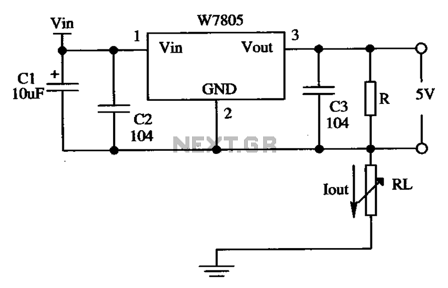
The circuit is composed of a W7805 positive current source application integration circuit that includes a voltage regulator. The W7805 regulator operates in suspension. A resistor is placed between its output terminal and the common terminal, forming a constant...

The circuit is designed to fit snugly, eliminating the need for adhesive. It is recommended to test the fit multiple times, making incremental adjustments until a snug but movable fit is achieved. The entire circuit should be placed inside...
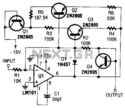
This operational amplifier circuit utilizes resistor and transistor feedback elements to function as a nonlinear amplifier. The resistors R4 and R6 can be adjusted to modify the breakpoints as needed. This operational amplifier circuit is designed to operate within the...
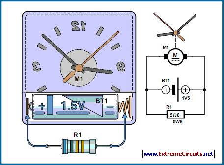
The circuit described is suitable for indicating the capacity of a battery using a low-cost electric clock. By connecting a resistor across the battery terminals, the battery discharges at a faster rate than it would with the clock alone....
This site addresses a range of subjects pertaining to circuits and electronics. Some of the topics discussed on this site include: * Alternating Relay Switch * Photoswitch Relay. The site serves as a comprehensive resource for understanding various electronic components...
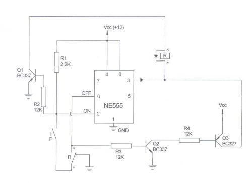
PWM waveforms are widely utilized to regulate the speed of DC motors. The duty cycle of the digital waveform can be established either through an adjustable analog voltage level (as seen in a NE555-based PWM generator) or through digital...