
breadboard How does current flow through this Arduino circuit

In an Arduino circuit, the 5V pin serves as a power output, providing a stable voltage supply to various components connected to the breadboard. The positive rail of the breadboard is typically used to distribute this voltage to multiple components, allowing for a common power source. When a wire is connected from the 5V pin to the positive rail, it establishes a pathway for current to flow from the Arduino to any devices or components that require power.
For effective current flow, it is essential to ensure that the positive rail is connected to devices such as sensors, LEDs, or microcontrollers that can utilize the supplied voltage. If the positive rail is left unconnected, as indicated, there will be no current flow, rendering any connected components non-functional.
In addition to the 5V pin, the Arduino also features ground (GND) pins, which should be connected to the negative rail of the breadboard. This establishes a complete circuit, allowing current to flow from the 5V pin, through the connected components, and back to the Arduino via the ground connection. Proper connections are crucial for the functioning of any electronic circuit, and understanding the relationship between the voltage supply and the components is fundamental to circuit design and implementation.
For those unfamiliar with electronic terminology, it may be beneficial to explore basic concepts such as voltage, current, and resistance, as well as the function of breadboards in prototyping circuits. This foundational knowledge can aid in effectively utilizing Arduino and similar platforms for various electronic projects.It seems to me like the wire connected to the 5v pin is connected to the + pins of the breadboard. which are connected to nothing. There`s nothing else on the + column. I know this is a basic "google it" question, but probably due to the fact that I don`t have the vocabulary to do so I`ve not been able to find a description of current flow in an Arduino. 🔗 External reference
Related Circuits
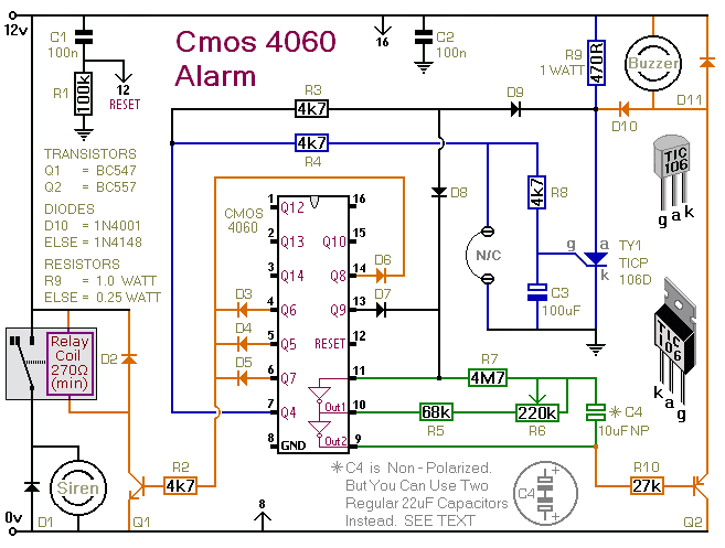
This is a single-zone alarm system featuring automatic exit, entry, and siren cut-off timers. It is designed to accommodate various types of normally-closed input devices, including magnetic reed contacts, foil tape, and passive infrared sensors (PIRs). Additionally, it is...

When the comparator's output transitions from low to high, the rising edge of the output pulse, differentiated by the Cl/Rl chain, activates Ql. This action blocks the comparator via its strobing input and maintains its output state for a...
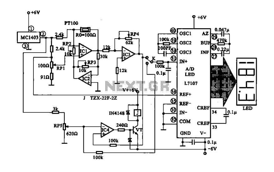
The digital display temperature detection circuit utilizes a precision digital display to indicate temperature readings. The circuit employs the MC1403, which outputs a reference voltage, with the potentiometer RP5 setting the reference value for the inverting terminal (a) of...
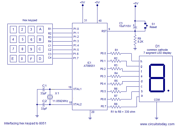
Interfacing a hex keypad to an 8051 microcontroller. The AT89S51 is utilized in this setup. A circuit diagram and assembly language program are included. A testing video is also provided. The interfacing of a hex keypad with the AT89S51 microcontroller...
The digital scoreboard circuit is designed to display numerical values ranging from 0 to 9 on a common anode 7-segment display. The circuit employs a 7-segment driver integrated circuit (IC), specifically the 74LS47 or 74LS247. A 555 timer IC...
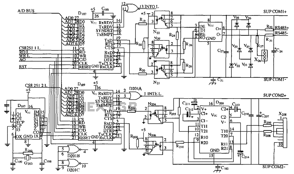
As shown in the figure, D187 is a universal asynchronous receiver-transmitter (UART). Its RX/TX signals are received through optocouplers N21, N22, and N29, facilitating RS-485 communication. The interface receiver/transmitter D28 and microprocessor D211 are completely optically isolated. D197 serves...