
how do you build a simple circuit to control a servo
The circuit for controlling a servo motor typically consists of a microcontroller, a power supply, and the servo motor itself. The microcontroller serves as the brain of the circuit, providing the necessary signals to the servo for position control. Commonly used microcontrollers for such applications include Arduino, Raspberry Pi, or any suitable embedded system that can output PWM (Pulse Width Modulation) signals.
The power supply must be capable of delivering the required voltage and current for the servo motor, which is generally in the range of 4.8V to 6V for standard servos. It is essential to ensure that the power source can handle the stall current of the servo, which can be significantly higher than the operating current.
The servo motor is connected to the microcontroller via a PWM signal pin. The microcontroller generates a PWM signal that varies in width, which corresponds to the angle of the servo arm. A typical PWM signal for servo control has a frequency of around 50 Hz, with pulse widths ranging from 1 ms (0 degrees) to 2 ms (180 degrees).
Additional components may include resistors for signal conditioning, capacitors for noise filtering, and possibly a transistor or relay if higher current handling is necessary for the servo operation. Proper grounding and decoupling techniques are crucial to ensure stable operation and to prevent any interference that could affect the servo's performance.
The layout of the circuit should be designed to minimize noise and ensure that the power supply lines are adequately decoupled from the signal lines. It is advisable to use a breadboard for initial testing before finalizing the design on a printed circuit board (PCB) for durability and reliability in practical applications.
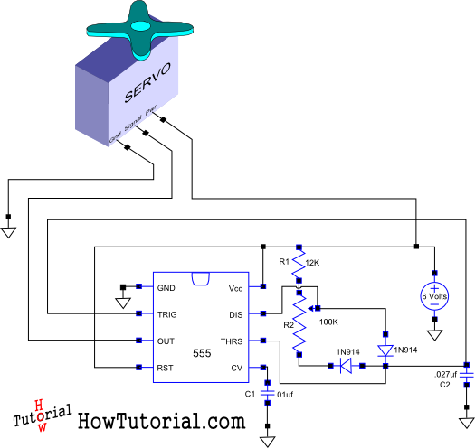
In summary, the design of a simple servo control circuit involves careful selection of components, proper signal generation through PWM, and attention to power supply requirements to achieve effective control of the servo motor.This is how I designed a simple circuit that allows you to control a servo and put it through its paces.. 🔗 External reference
Related Circuits
Logic power control of an analog regulator can be useful in applications where a digital circuit or controller needs to manage a power source, such as in EEPROM. In electronic systems, managing power effectively is crucial for the performance and...
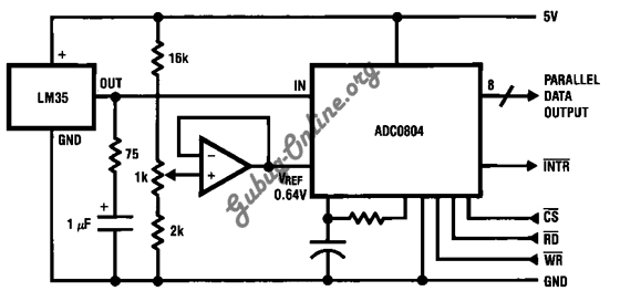
This is a design for a temperature-to-digital converter circuit that is controlled by the LM35 integrated circuit. The LM35 is a precision integrated circuit temperature sensor, whose output voltage is linearly proportional to the Celsius temperature. The circuit utilizes the...
If you need a timer circuit, we go after the most proven 555. However, if the delays are longer, based on timing capacitor capacity is too large. In this case, a circuit of Figure 1 After pressing the button...
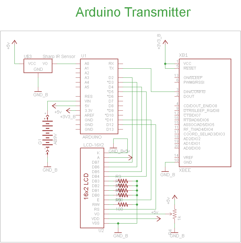
The schematic for the transmitter in this project consists of four main components: the Arduino UNO, the Sharp IR distance sensor, the XBee wireless modules, and a 16x2 LCD. The connections between these components are illustrated in the schematic....
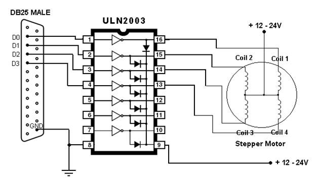
This article outlines the process of connecting a stepper motor to a computer's parallel port and writing code to control it using the scroll wheel of a mouse. For those unfamiliar with stepper motors, this project offers an engaging...
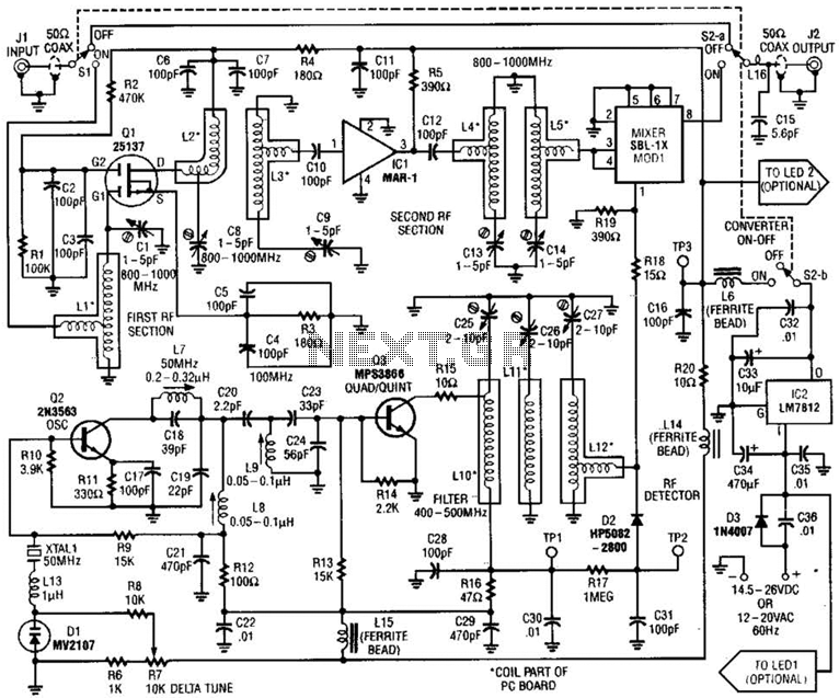
This converter allows the reception of frequencies ranging from 800 to 1000 MHz on any scanner that operates within the 400 to 500 MHz range. The converter can be configured to cover either the 800 to 900 MHz band...