
led flasher circuit schematic inside
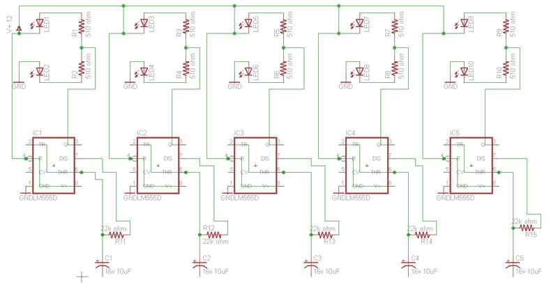
This circuit design aims to create a visually engaging LED flasher using five NE555 timer integrated circuits (ICs), which are widely recognized for their versatility in timing applications. Each NE555 timer will drive one pair of LEDs, allowing for independent control of the flashing rates. The use of trimmer potentiometers (trim pots) will enable fine-tuning of the flash rates for each LED pair, providing a customizable user experience.
The orientation of the LEDs is crucial for the desired operation of the circuit. The lower row of LEDs should be connected to the output of the NE555 timers in a way that allows them to illuminate when the output is high. Conversely, if the top row is meant to light up during a low output, the connections must be verified and corrected if necessary to ensure proper functionality.
In terms of component selection, the NE555 timer requires bypass capacitors for stable operation. According to the datasheet, each timer should have a 0.1 µF ceramic capacitor connected between the supply pin and ground to filter high-frequency noise. Additionally, a larger capacitor of at least 1 µF should be included for further stabilization. The entire circuit benefits from a 100 µF capacitor, which acts as a reservoir to smooth out fluctuations in the power supply, particularly when powered by a PC power supply. While PC power supplies generally provide stable voltage, incorporating this capacitor can enhance performance by further reducing any residual noise.
The layout of the trim pots should be strategically placed within the circuit to allow easy access for adjustments. The values for these pots can be determined through experimentation, typically starting with values in the range of 10 kΩ to 100 kΩ, depending on the desired range of flash rates. It is advisable to simulate the circuit in Eagle or similar software to visualize the effects of varying the trim pot values on the LED flashing rates.
In conclusion, this circuit design not only serves as a practical exercise in using NE555 timers but also provides a platform for learning about component selection, circuit layout, and the importance of proper schematic representation. Careful attention to the orientation of the LEDs and the inclusion of necessary bypass capacitors will ensure reliable operation and an engaging visual display.Build a circuit that will flash 5 pairs of LEDs at variable rates. To do this I designed a circuit using 5 NE555 timers. To control the variable flash rate I want to use trim pots. I am having a hard time figuring out where to lay out the trim pot and what value to use. Can some one please help me I have attached a screen cap of the schematic I designed in eagle. I`ve had a couple of beers, so maybe I`m not seeing this right, but it looks to me as if the top row of Leds are the wrong way round. It looks like the lower row will light when the output is high, but if the top row is meant to light on output low, they are the wrong way round. Thanks for the replies guys. As I said I am very new to this and designed the schematic in eagle after watching a few tutorials. I am basing my electronics knowledge off of 3 electronic classes I took back in high school. After 7 years the knowledge gained in those classes has faded somewhat. The season I had not completed the circuit is because I was waiting on figuring out what value trimpot to use.
The tutorial I spoke of was a tutorial on how to use Eagle, not on the flasher circuit. My current knowledge on circuit design comes from some classes taken back in high school and most recently reading a few of Forrest Mims books. Your schematic is a negative. I fixed it. You saved it as a fuzzy JPG file type instead of as a very clear GIF or PNG file type so that is why it looks fuzzy.
The datasheet for the LM555 shows two supply bypass capacitors. A 0. 1uf ceramic disc and at least 1uF. Each 555 should have a 0. 1uF ceramic disc and the entire circuit should have 100uF. I have the background set to black in Eagle. I am a professional photographer and almost all of my photo editing work is done on a black background as it is much easier on the eyes. When I found out I could change the workspace in eagle to black I did. I just was to lazy to change it back to white before taking the screen cap. I saved it as a quality 90 jpg and on 4 of my computers it looks fine, but for every ones convenience I will save them as.
gif from now on. This circuit will be powered by a pc power supply so is the 100uF necessary to filter out noise or does the pc power supply do a good job of filtering anyway 🔗 External reference
Related Circuits
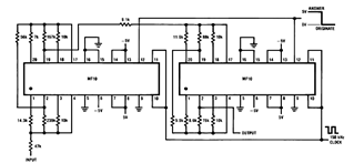
Later, there will be applications including a Basic Circuit Description, Block Diagram of the MF10, Programmable Dual Clock Generator, Butterworth Lowpass Filter, MF10 as an Input Filter and Sample/Hold, Generating Quadrature Sine Waves, and the Non-Inverting Integrator used in...

RTD sensors are measured using a precision 24-bit analog-to-digital converter (A/D) that includes a built-in programmable gain amplifier. The connections for 2-wire, 3-wire, and 4-wire RTDs are illustrated. This setup facilitates the connection and measurement of RTDs with amplifiers and...
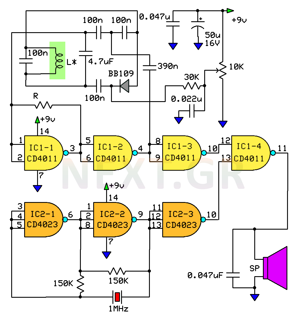
This circuit is a metal detector designed to detect large metallic objects at depths ranging from 2 to 3 meters, depending on the size of the object and the type of soil. The construction is straightforward, making it accessible...
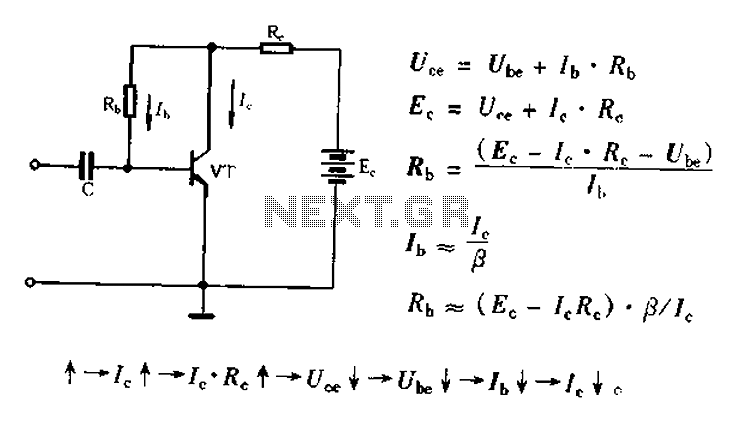
Bias voltage negative feedback circuit The bias voltage negative feedback circuit is a crucial component in various electronic applications, particularly in amplifiers and oscillators. This circuit is designed to stabilize the operating point of a transistor or operational amplifier by...
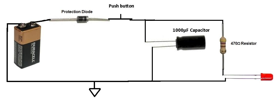
This project involves charging a capacitor with voltage, which will subsequently serve as a temporary power source for the circuit. After charging the capacitor with a battery, the battery is disconnected from the circuit. The capacitor then provides current...

The thermistor RT, along with resistors R1, R2, R3, and variable resistor RP1, creates a temperature measurement bridge. At a temperature of 20°C, the configuration of R1, R3, and the adjustment of RP1 enables the bridge to maintain balance....