
MF10 Full Duplex Modem Filter Diagram Schematic and Applications

The MF10 is a versatile integrated circuit that functions in various applications, particularly in signal processing and conditioning. The basic circuit description of the MF10 outlines its operational capabilities, including its dual-input and dual-output configuration, which allows for complex signal manipulation.
The block diagram of the MF10 illustrates the internal architecture, highlighting key components such as operational amplifiers, comparators, and signal routing paths. This visual representation aids in understanding how the circuit processes input signals to produce desired output characteristics.
The Programmable Dual Clock Generator feature of the MF10 enables precise timing control for synchronous operations. This functionality is crucial in applications requiring coordinated timing, such as digital signal processing and communication systems.
The Butterworth Lowpass Filter design implemented in the MF10 provides a smooth frequency response with minimal ripple, making it ideal for applications that demand high fidelity in signal transmission. The filter's characteristics can be adjusted through external components to meet specific frequency requirements.
As an Input Filter and Sample/Hold circuit, the MF10 is capable of capturing and holding sampled values of analog signals, ensuring that digital systems receive stable and accurate data for further processing. This function is particularly important in data acquisition systems where signal integrity is paramount.
Generating Quadrature Sine Waves is another application of the MF10, which is essential in various modulation schemes and signal generation tasks. The circuit can produce two sine waves that are 90 degrees out of phase, facilitating the creation of complex waveforms.
The Non-Inverting Integrator used in the MF10 allows for the integration of input signals without inverting their phase, providing a straightforward means of signal manipulation in analog applications. This configuration is particularly useful in applications such as analog computing and waveform shaping.
Overall, the MF10's diverse applications and functionalities make it a crucial component in modern electronic systems, providing engineers with the tools necessary for effective signal processing and manipulation.You will find later some applications such as Basic Circuit Description, Block Diagram of the MF10, Programmable Dual Clock Generator, Butterworth Lowpass filter, MF10 as an Input Filter and Sample/Hold, Generating Quadrature Sine Waves, and the Non-Inverting Integrator Used in the MF10 🔗 External reference
Related Circuits
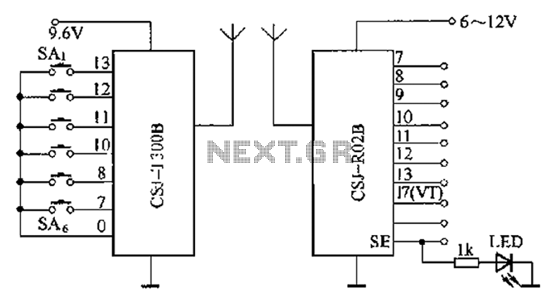
The CSJ-T300B/CSJ-R02B is an enhanced digital encoding and decoding circuit developed based on the CSJ-T300A/CSJ-R02A. It forms a remote control circuit that includes the CSJ-T300B and CSJ-R02B components, as illustrated below. The CSJ-T300B/CSJ-R02B circuit architecture is designed to facilitate improved...
Most operational amplifier circuits require a dual-polarity power supply - one having +V and -V. However, there are times when a DP supply simply isn't conveniently available. Single-polarity modifications to DP designs often achieve their effect by referencing the...

This circuit schematic produces a beep and/or illuminates an LED when someone touches the door handle from outside. The alarm will continue to sound until the circuit is switched off. The circuit operates on the principle of capacitive sensing, where...
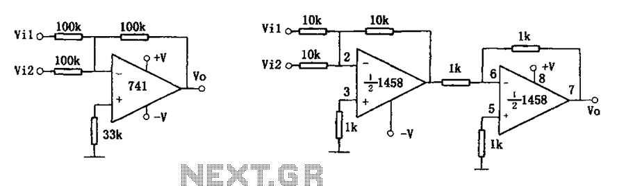
The common addition circuit is illustrated, with Figure (a) depicting the inverting adder circuit. The input-output relationship is expressed as Vo = -(Vi1 + Vi2). For phase addition, the circuit shown in Figure (b) can be utilized, with the...
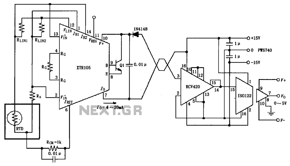
The RTD temperature sensor, as illustrated in the subsequent figure, collects temperature data from the field. This data is converted into a voltage signal by the XTR105, which is then transformed into a 4 to 20 mA current output....
One application of this handy circuit is a graphic equalizer, created by feeding a signal to a number of parallel band-pass filters each tuned to a different frequency; typically octaves apart. Then, you can adjust the strength in each...