
make a simple ic 741 smoke detector circuit schematic diagram enclosed
This smoke detector circuit is designed for simplicity and effectiveness in detecting smoke and potentially harmful gases. The FIGARO TGS 813 gas sensor operates by measuring changes in resistance when smoke particles are present in the air. This sensor is known for its sensitivity to a variety of gases, making it suitable for smoke detection applications.
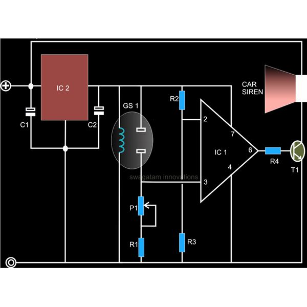
The comparator stage, implemented with the operational amplifier IC 741, serves to compare the voltage level from the gas sensor with a reference voltage. When smoke is detected, the sensor's output voltage changes, causing the output of the comparator to switch states. This transition indicates the presence of smoke and can be used to trigger further actions.
The output from the comparator can be configured to control a relay, allowing for the integration of additional fire control systems, such as fire alarms or suppression systems. Alternatively, the output can be connected to a car siren or similar alarm device, providing an audible warning to alert individuals in the vicinity of the potential danger.
In constructing this smoke detector circuit, careful attention should be paid to the power supply requirements for the IC 741 and the gas sensor, as well as the characteristics of the relay or alarm device used. Proper calibration of the reference voltage at the comparator input may also be necessary to ensure reliable operation and sensitivity to smoke detection. Overall, this circuit offers a practical solution for smoke detection in various environments, enhancing safety and response capabilities.A very simple to build smoke detector circuit has been discussed here through a schematic diagram, which can be easily built and installed over an area for the necessary detection purposes. The circuit incorporates the versatile FIGARO TGS 813 gas sensor as the main sensing device. The detections made by the sensor is translated into a logic status through a comparator stage composed of the IC 741.
The generated warning signal is either integrated to a relay for triggering a fire control system or simply to a car siren for the required alarm.. 🔗 External reference
Related Circuits

This circuit is intended for precision centigrade temperature measurement, with a transmitter section converting to frequency the sensor's output voltage, which is proportional to the measured temperature. The output frequency bursts are conveyed into the mains supply cables. The...

There is no PCB since there are no components to mount on one. The object was to create a source of ultraviolet light as fast as possible. The UV tubes I bought from a lighting shop for use with...

The diagram illustrates a straightforward voltage stabilizer design capable of handling significant output power in the range of 5 to 10 KVA. The implementation of solid-state relays (SSRs) simplifies the output stage configuration and enhances accuracy, owing to modern...

The circuit is designed for a broadband linear detection application with a bandwidth of 10 MHz. It serves as a millivoltmeter measuring instrument suitable for frequencies exceeding 10 MHz. The circuit features a linear detector utilizing operational amplifiers, specifically...

The uPC1237 operates with a single power supply, with an operating voltage range of 25V to 60V, typically used directly as a positive power source (+Vcc) for amplifiers. The relay coil voltage is 24V DC, and the relay driver...

An amplifier designed to achieve a voltage gain of approximately 20, utilizing the MPS6517 PNP transistor in the emitter follower configuration. The RI controller allows for adjustment of the transistor's quiescent point. The output signal is activated only when...