
metal detector circuit

The metal detector circuit utilizes a Colpitts oscillator configuration, which is particularly effective for this application due to its ability to generate a stable frequency. The circuit consists of a transistor, capacitors, an inductor, and a power source. The transistor is used to amplify the oscillations produced by the Colpitts configuration, while the inductor (L1) and capacitors form the resonant tank circuit that determines the frequency of operation.
In this design, L1, consisting of 60 turns of #36 enameled copper wire wound on a 1 cm PVC tube, plays a crucial role in tuning the oscillator. The choice of wire gauge and the number of turns directly influence the inductance value, which, along with the capacitors, sets the oscillation frequency in the AM band.
To ensure optimal performance, it is essential to use a high-quality AM receiver, as this will enhance the ability to detect the oscillations emitted by the metal detector circuit. When the circuit is powered by a 6V or 9V battery, it operates quietly without the interference that a power supply might introduce.
As the metal detector nears a metallic object, the oscillation frequency changes, causing a variation in the signal picked up by the AM radio. This results in the audible hissing sound, indicating the presence of metal. The simplicity of the design makes it an ideal project for electronics enthusiasts, providing a practical application of basic electronic principles while demonstrating the functionality of oscillators in detecting metallic objects.This is a project of a simple metal detector circuit. The circuit is easy to build using only one transistor and few other components. The circuit is a colpitts oscillator which boradcast on AM band. Take a good quality am receiver and place it near this circuit and search the signal in your radio, when the radio found the signal you will hear no sound. Now when you place this metal detector circuit near any metal object you will hear hissing sound from your AM radio. L1 is equal to 60 turns of #36 enameled copper wire wound on 1cm PVC tube. A 6V or 9V battery should be used to power the circuit. Do not use power supply to power the circuit it will create noise. 🔗 External reference
Related Circuits

A schematic diagram for a broadband QRP SWR metering circuit intended for use in a QRP antenna tuner. The circuit allows the user to press a momentary DPDT switch to observe an LED indicator while adjusting the capacitors of...
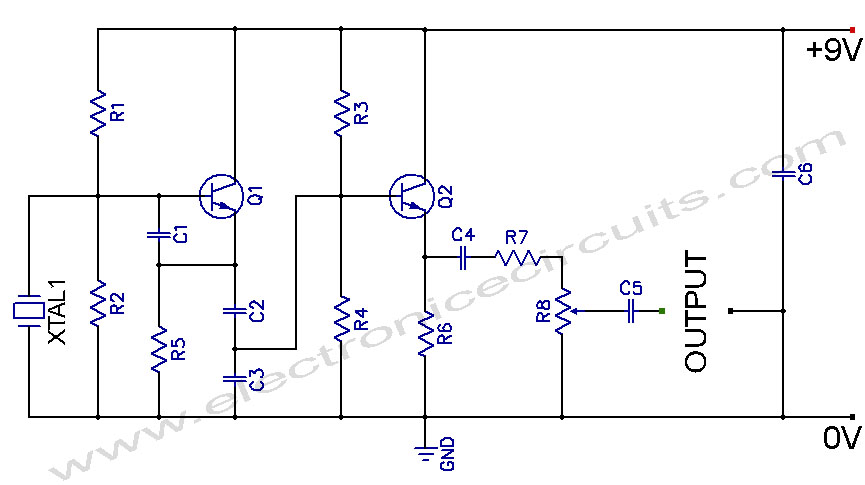
Crystal Controlled Oscillator Circuit. This general-purpose signal source is highly effective in signal-tracing applications. The output level is adjustable. The crystal-controlled oscillator circuit is designed to provide a stable and precise frequency output, which is essential for various electronic applications,...
Nissan Sentra 1.6 Liter Manual Transmission Starter Circuit Wiring Diagram. The Nissan Sentra 1.6 Liter manual transmission starter circuit wiring diagram provides a visual representation of the electrical connections involved in the starting system of the vehicle. This diagram is...

This second-order filter, designed for audio applications, utilizes an LM1458 or a similar operational amplifier. It is tunable with a cutoff frequency ranging from 30 Hz to 300 Hz. The resistors R2a and R2b are ganged log-taper potentiometers. The described...
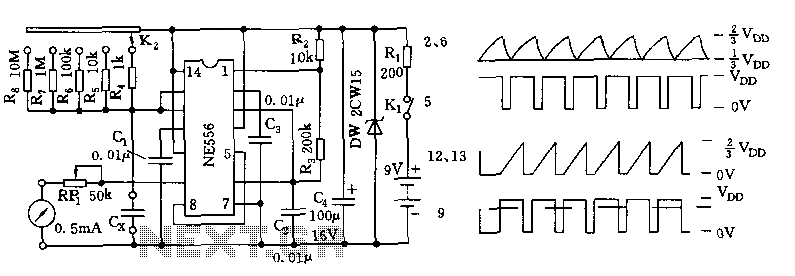
The tester comprises a dual time base circuit using a 556 timer and various RC components. The right side of the circuit features the 556 timer (556 1/2) along with resistors R2, R3, capacitors C2, C3, and additional components...
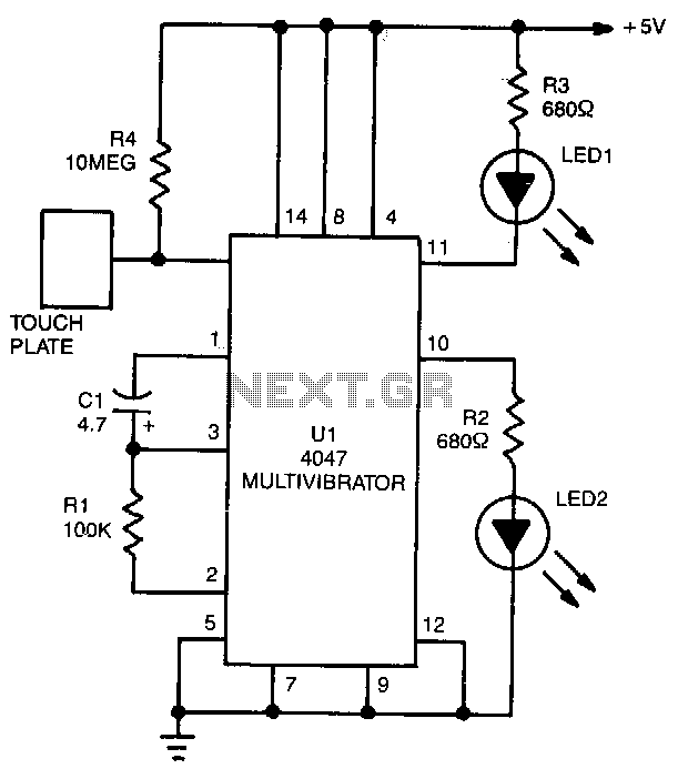
LED1 and LED2 indicators activate and stay illuminated each time the circuit is triggered. During the timing cycle, the Q output at pin 10 of U1 becomes positive when the Q output at pin 11 turns negative. The two...