
motion detector sensor circuit

This motion detection sensor circuit is designed to detect movement by utilizing infrared technology. The transmitter section comprises an NE555 timer configured in astable mode, which generates a square wave signal at a frequency of 5 kHz. This signal drives an infrared LED that emits modulated infrared light. The modulation helps to distinguish the infrared signal from ambient light, enhancing the sensor's performance in various lighting conditions.
The receiver section consists of a phototransistor that is sensitive to the infrared light emitted by the transmitter. When the infrared light is interrupted by a moving object, the phototransistor's output changes state. In the absence of motion, the LM1458 operational amplifier maintains a low output on pin 7, indicating no detection. However, when motion is detected, the phototransistor allows current to flow, resulting in a high output (5 volts) from the LM1458.
This output can be utilized to trigger an alarm or alert system, such as a buzzer or speaker, providing an audible indication of motion detection. The circuit layout can be implemented on a printed circuit board (PCB), which simplifies construction and ensures reliable connections between components. The PCB design is available for download, allowing for easy replication of the motion detection sensor circuit. This design is suitable for various applications, including security systems, automated lighting, and occupancy detection.This circuit is a motion detection sensor, this circuit uses a light source and detector as a sensor infrared motion detector. Motion sensor using infrared LED and phototransistor. Because it uses light to the sensor sensitivity can be affected by environmental disturbances, such as wind, waste, or stray light.
In this schematic is divided into t wo schematic transmitter and receiver. Transmitter circuit is controlled by the NE555. NE555 astable multivibrator configuration installed. Infrared LED mounted on the output of a schematic and generate a frequency of 5 kHz. Here is a schematic drawing of motion detection sensor transmitter: At the receiver circuit of the LED infrared light captured by the phototransistor. At normal conditions ie when the sensor does not detect motion, LM1458 output on pin 7 will be value low (0 volts).
if the sensor detects movement, the LM1458 IC output on pin 7 will be value high (5 volts). IC LM1458 output can be connected with a speaker, buzzer or alarm. Here I also include a PCB (printed circuit board) of the motion detector sensor circuit and you can also download it. 🔗 External reference
Related Circuits
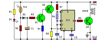
In this fire alarm circuit, a thermistor functions as the heat sensor. As the temperature rises, its resistance diminishes, and conversely, when the temperature falls, its resistance increases. At standard temperature, the resistance of the thermistor (TH1) is approximately...
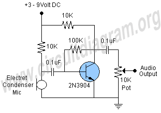
This schematic illustrates a highly sensitive microphone preamplifier circuit designed to amplify the gain of a microphone or enhance audio signals originating from a microphone. The circuit is straightforward, comprising only a few components, and can be assembled in...
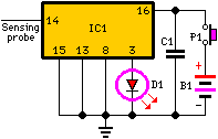
When the unit is positioned near a live conductor, whether insulated or buried in plaster, capacitive coupling occurs between the live conductor and the probe. This interaction activates the counter, resulting in the LED flashing five times per second,...
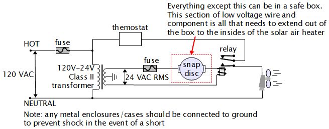
For various experiments, such as solar air heaters, an automatic fan activation and deactivation system is required. A straightforward solution is to use a bimetal snap disc thermal sensor. This sensor functions as a switch that closes when a...

An oscilloscope front-end amplifier can be constructed using low-cost transistors and video amplifier integrated circuits (ICs). This preamplifier utilizes a FET input along with compensated attenuators, achieving an approximate bandwidth of 100 MHz, which is sufficient for most general-purpose...
The use of programming pods has become a standard practice in manufacturing, particularly during the early development stages of firmware for new products. Once visual and structural tests are completed, the board is prepared for full functional testing. The...