
short circuit diagram
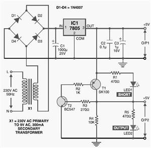
No description available.
Related Circuits
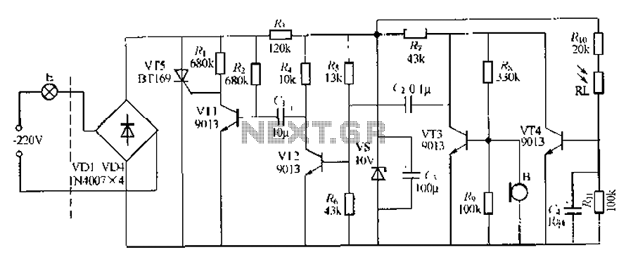
This circuit describes a sound and light control delay system for a walkway stairs light switch. It involves various components including 220V AC electric bulbs, diodes (VD1-VD4), and resistors. The circuit utilizes a rectifier regulator to stabilize the voltage...
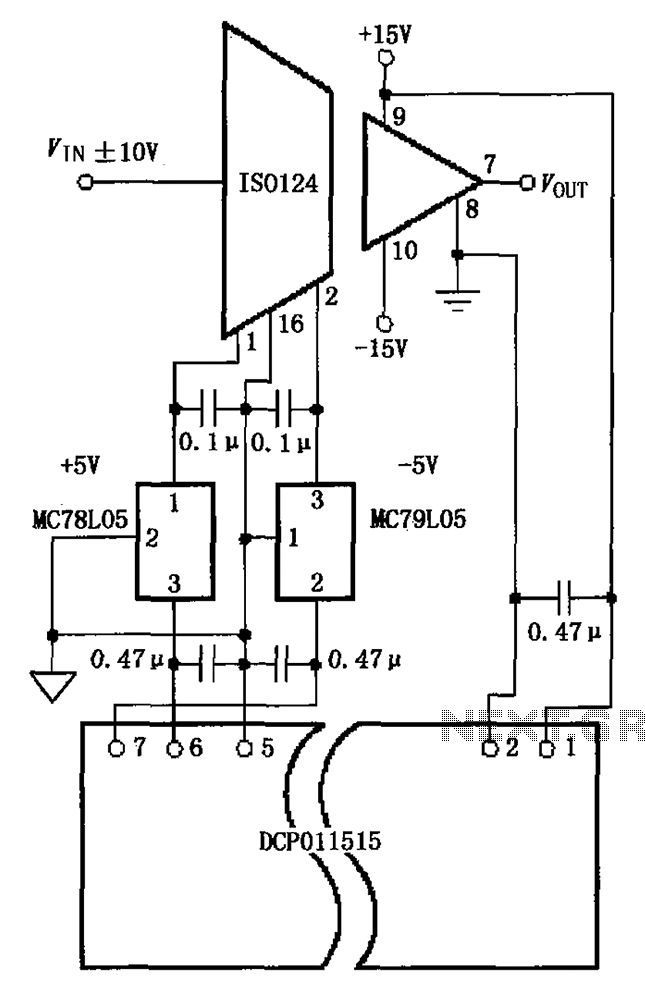
The circuit depicted in the figure includes the ISO124 and MC78L05 components, along with an external regulator, MC79L05, and the DCP011515, which collectively enhance the power supply rejection ratio (PSR) of the circuit. The input signal, VIN (maximum swing...
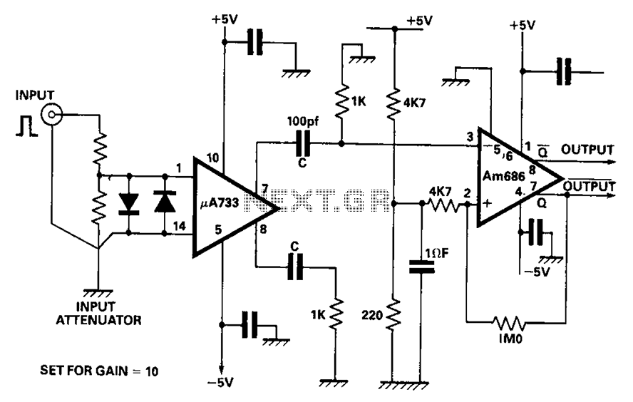
A video amplifier output arrives at a differentiation stage before the Schottky comparator. The typical propagation delay is reduced to 10 ns. The output pulse width is determined by the capacitance value, where C is 100 pF, resulting in...
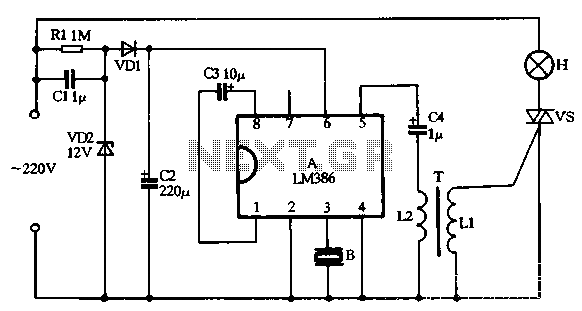
VD1, VD2, C1, and C2 comprise a simple half-wave rectifier capacitor step-down voltage regulator circuit, providing an output of approximately 12V for a linear power supply connected to the LM386. The LM386 is linked to the inverting input terminal...
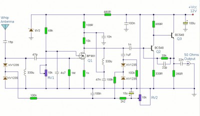
This is a booster antenna circuit designed for frequencies ranging from 550 kHz to 1650 kHz, aimed at amplifying signals received from a telescopic antenna. It covers the medium waveband within this frequency range. To drive low impedance (50...
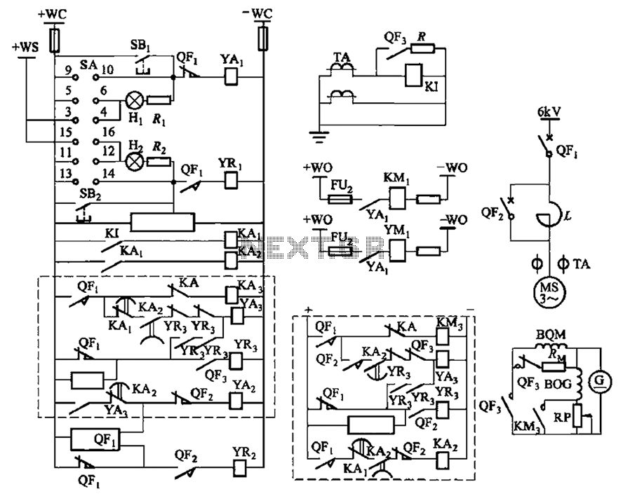
The circuit depicted in Figure 3-189 includes various components such as switch SA, closing button SBi, trip button SBz, de-excitation switch Yaa, and off trip coil YR3. The excitation switch contacts are represented by QF3, which serves as a...