
Synchronous electric motor chokes down according to the stator current excitation circuit

The circuit in Figure 3-189 is designed to control a power synchronous motor using a combination of switches and circuit breakers that ensure safe and efficient operation. The main components include various switches for excitation and de-excitation, as well as circuit breakers that protect the system during operation.
At the initial stage, the synchronous motor is powered through a reactance (L) which allows for a gradual increase in speed, preventing sudden inrush currents that could damage the motor. Once the motor reaches synchronous speed, circuit breaker QFz is engaged to bypass the reactance, allowing the motor to operate under full voltage conditions, which is essential for optimal performance.
The excitation switch QF3 plays a critical role in managing the excitation current supplied to the motor. By closing this switch, the system disconnects the de-excitation resistance (RM), allowing the exciter to energize the motor's field winding. This process is crucial for maintaining the magnetic field necessary for the synchronous operation of the motor.
In the event of a fault or an overload condition, circuit breaker QFa is designed to trip, effectively removing the exciter from the motor field circuit. However, the configuration ensures that the magnetoresistance RM still influences the field circuit, facilitating a controlled de-excitation process rather than an abrupt shutdown, which could lead to mechanical stress on the motor.
The rheostat RP allows for fine-tuning of the excitation current, providing flexibility in the motor's performance characteristics. This adjustment capability is essential for applications requiring precise control over the motor's torque and speed.
The virtual circuits indicated in the schematic serve as visual aids for operators, providing a clear representation of the control mechanisms involved in starting and resuming the automatic control of the motor. This design enhances operational safety and efficiency, ensuring that the motor can be started and stopped without risk of damage or operational disruption. Circuit shown in Figure 3-189. Figure, SA controls switch; SBi is closing button; SBz to trip button; Yaa de-excitation switch is closing coil; YR3 is off trip coil magnetic sw itch; figure, for the excitation switch contacts QF3 each touch point. Excitation switch, a circuit breaker is made with the restructuring. Power synchronous motor is controlled by the circuit breaker QFi. When you start, disconnect breaker QF2, synchronous motor through the reactance L is step-down start until the motor reaches synchronous speed and quasi or more, closing the circuit breaker QFz shorting reactor L, the synchronous motor running at full pressure. When the excitation switch QF3 closing, the normally closed contacts disconnect de-excitation circuit resistance RM, exciter for synchronous motor into line excitation; when QFa trip exciter exits synchronous motor field circuit, but will destroy magnetoresistance RM access synchronous motor field circuit will be de-excitation.
Excitation current size can be changed by adjusting the rheostat RP. in graph. Marked virtual circuit is a light box to start the control circuit; labeled virtual circuit frame for the resumption of automatic control circuit.
Related Circuits
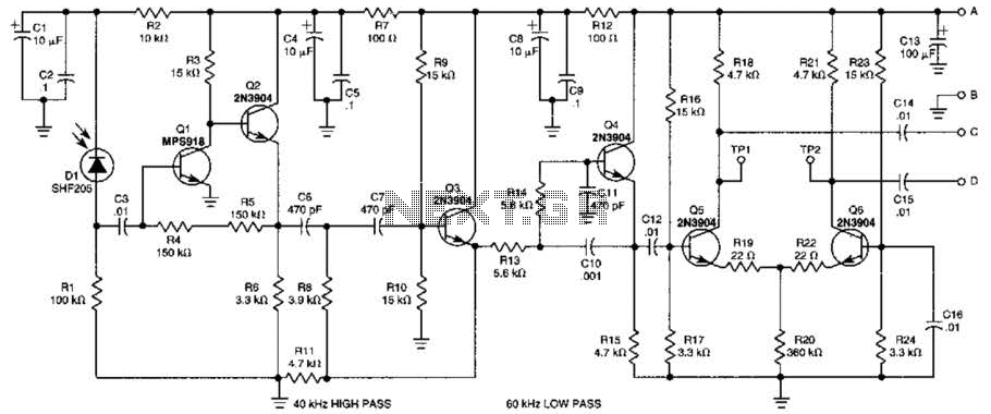
This receiver is designed to detect infrared (IR) or light beams that are frequency modulated on a 50-kHz carrier. The transistors Q2, Q1, Q3, and Q4 form an active filter and amplifier, while the differential amplifier formed by Q5...
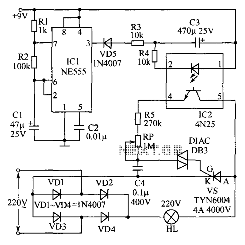
This circuit features an appealing Christmas lights setup. Upon activation, the lights (HL) gradually increase in brightness. Once they reach maximum brightness, they automatically dim, and upon reaching the lowest brightness, they gradually brighten again, creating a smooth transition...
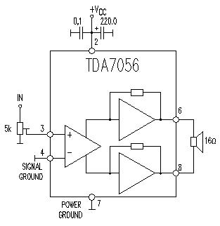
This TDA7056 power audio amplifier circuit diagram project is designed to deliver a maximum output power of 1 watt into an 8-ohm load when powered by a 6-volt supply, or a maximum output power of 3 watts into a...
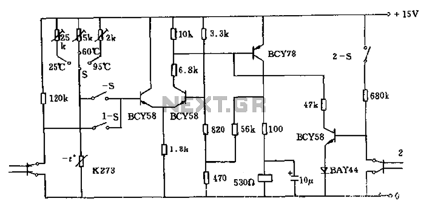
The circuit utilizes a thermistor (K273) to monitor temperature levels and control a relay based on the immersion of two sensor electrodes in a liquid. When the temperature reaches a predetermined threshold, the relay activates to heat the liquid....
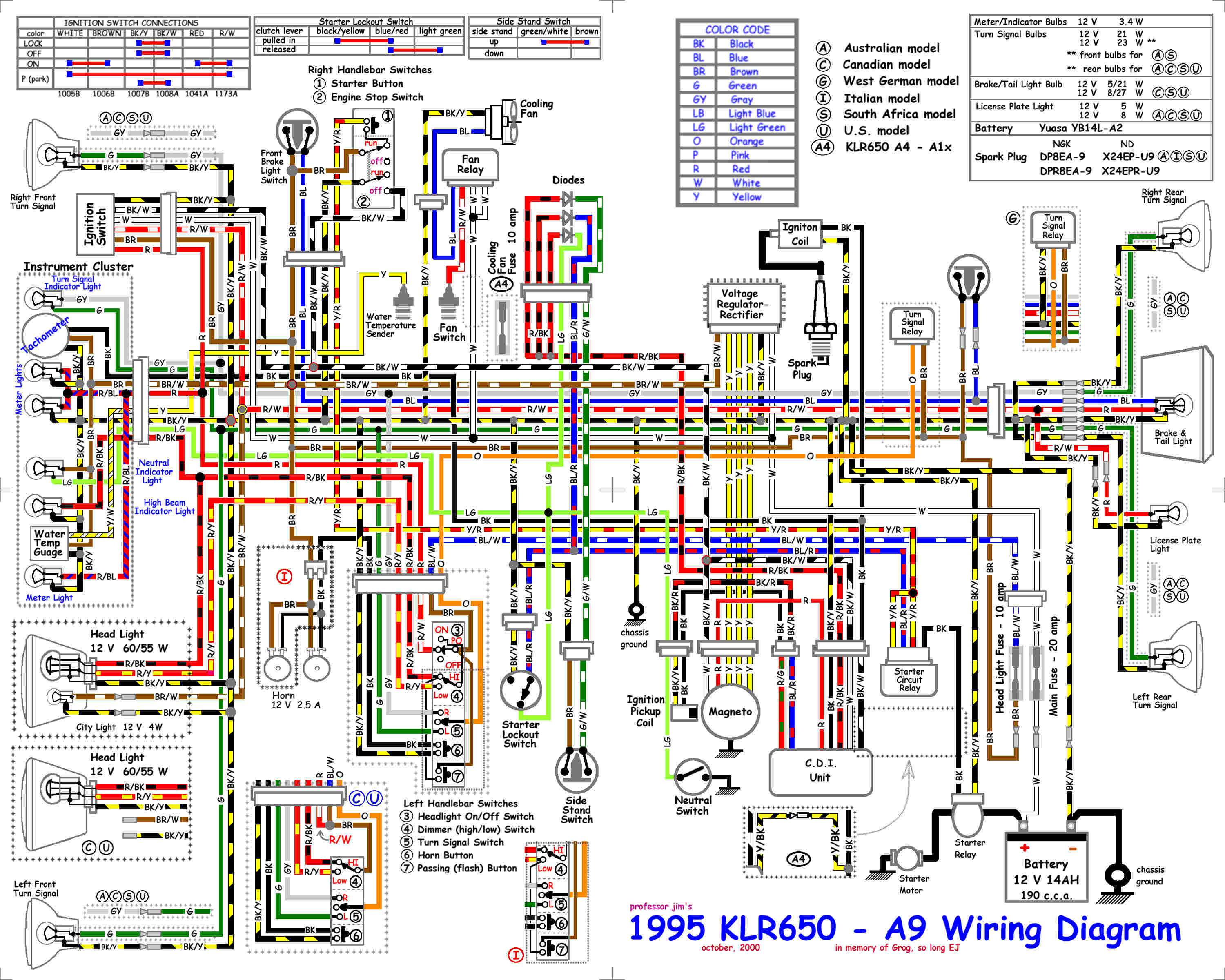
The following circuit illustrates the electrical wiring diagram for the KLR650 motorcycle. It is characterized by reliability, good overall performance, ease of maintenance, and features a four-stroke DOHC dual-counter balanced, single-cylinder, water-cooled engine that produces a claimed 44 hp...
The individual has been engaged in garden railroading for just over a year, utilizing skills from various hobbies. They have designed and built two scratch-built bridges and nearly 100 trestle bents to support a 200-foot main line. Their interests...